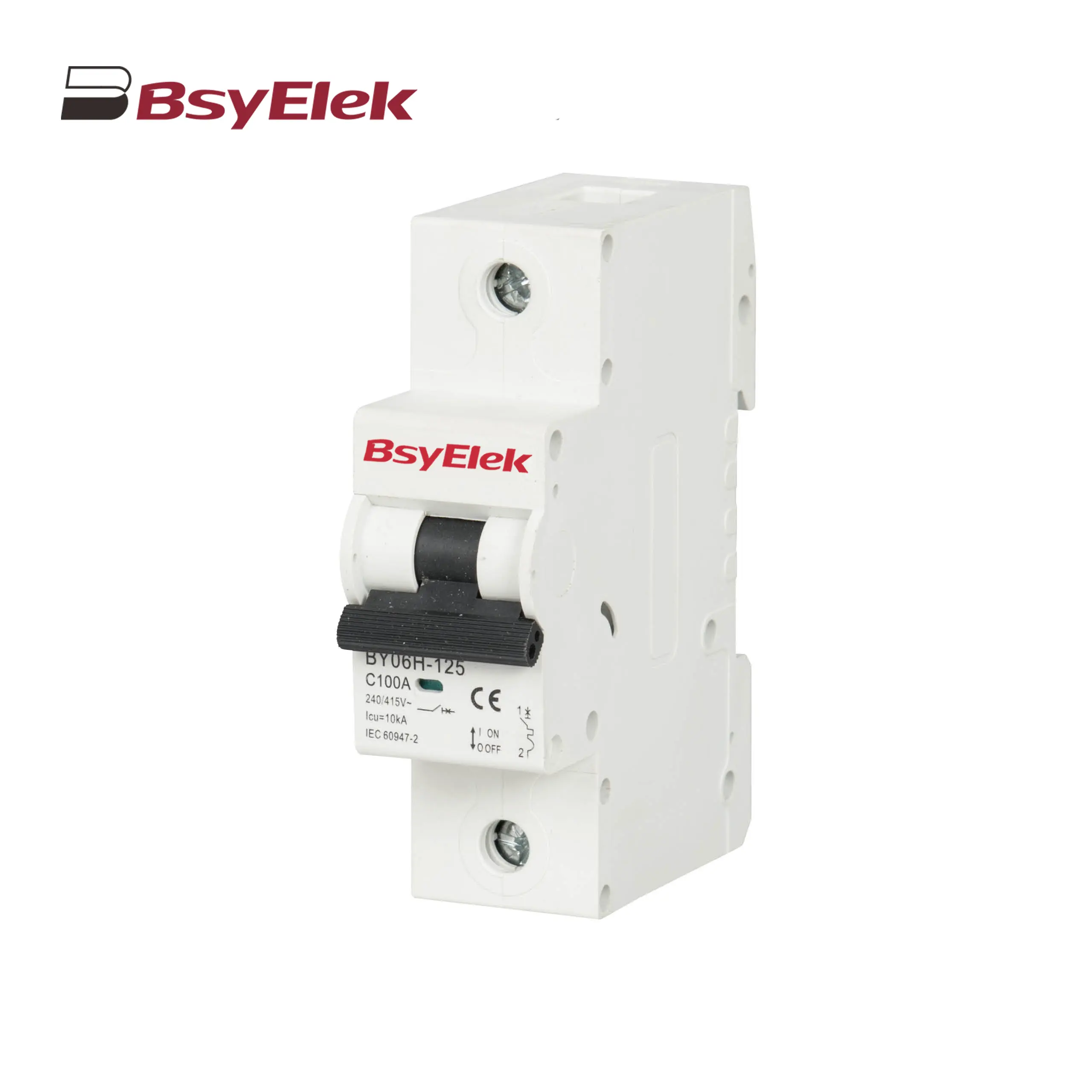
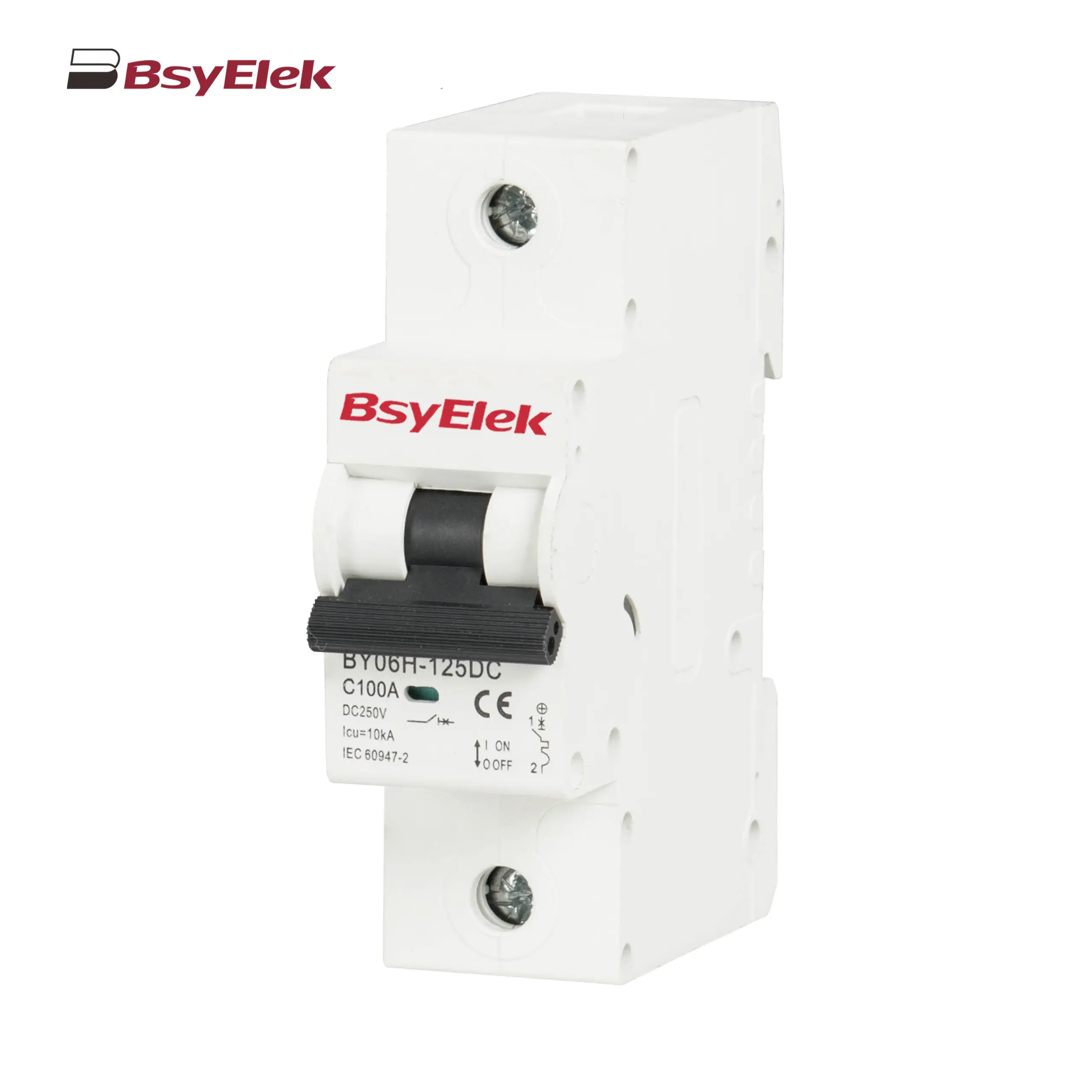
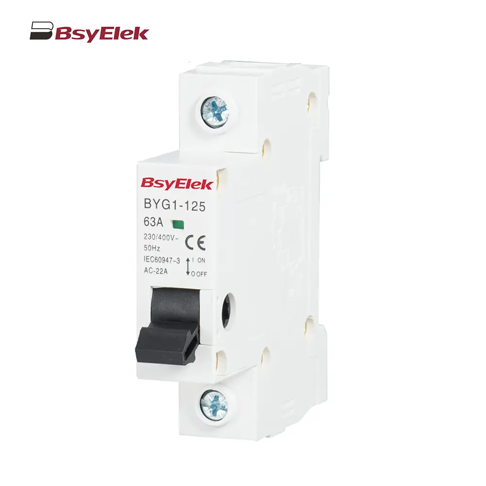
BY06H-125 MCB 10-15KA Miniature Circuit Breaker
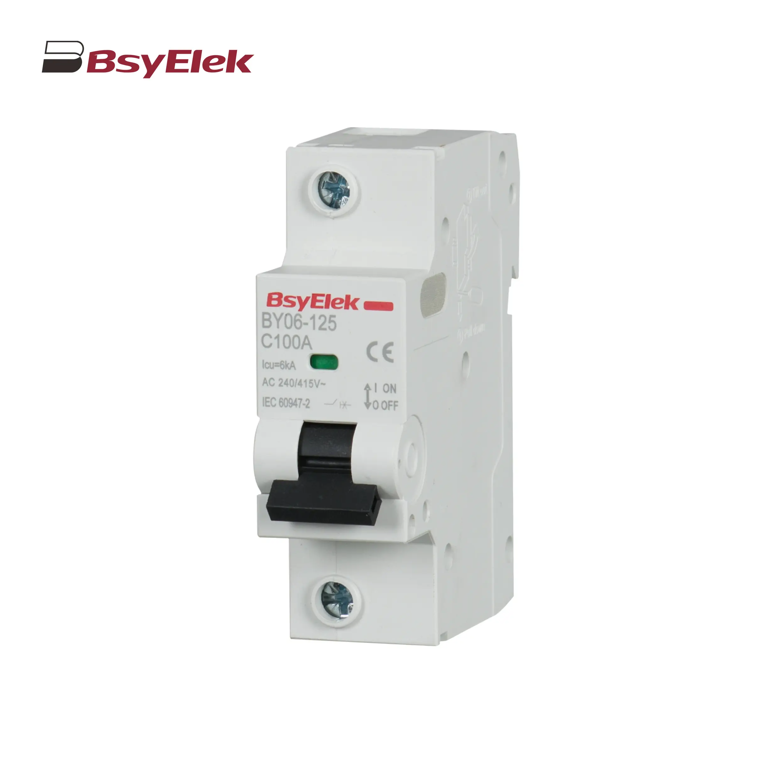
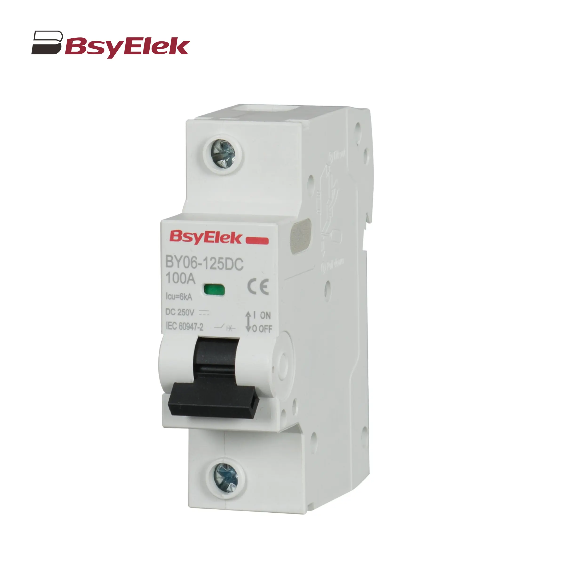
BY06-125 MCB 6KA Miniature Circuit Breaker
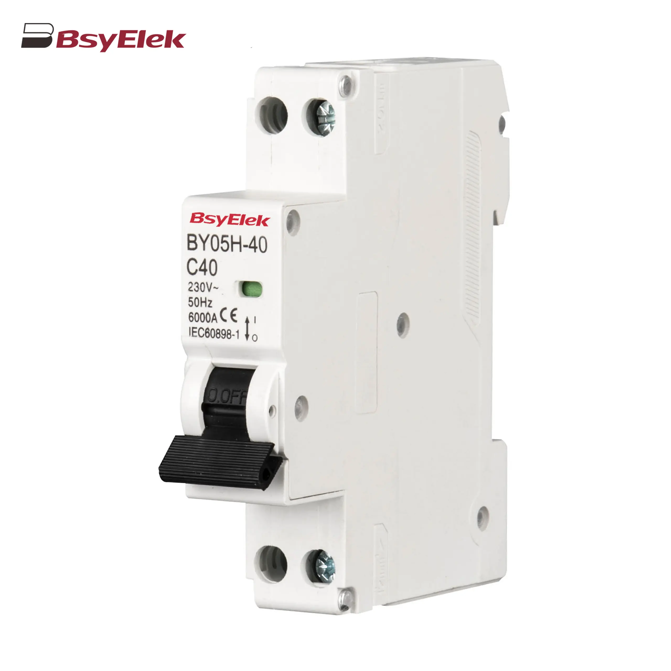
BY05H-40 MCB Single Modular 6KA Miniature Circuit Breaker
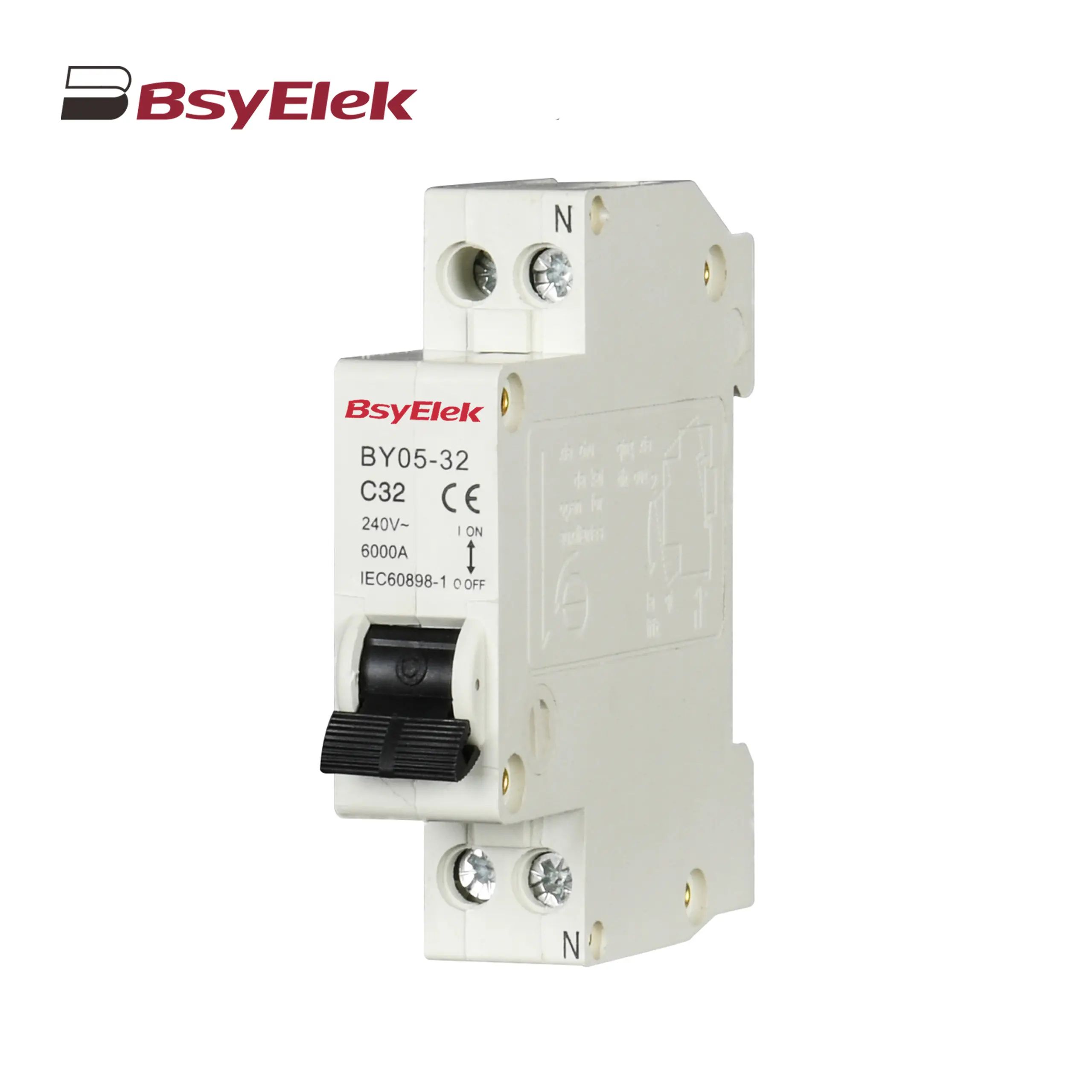
BY05-32 MCB Single Modular 3KA Miniature Circuit Breaker
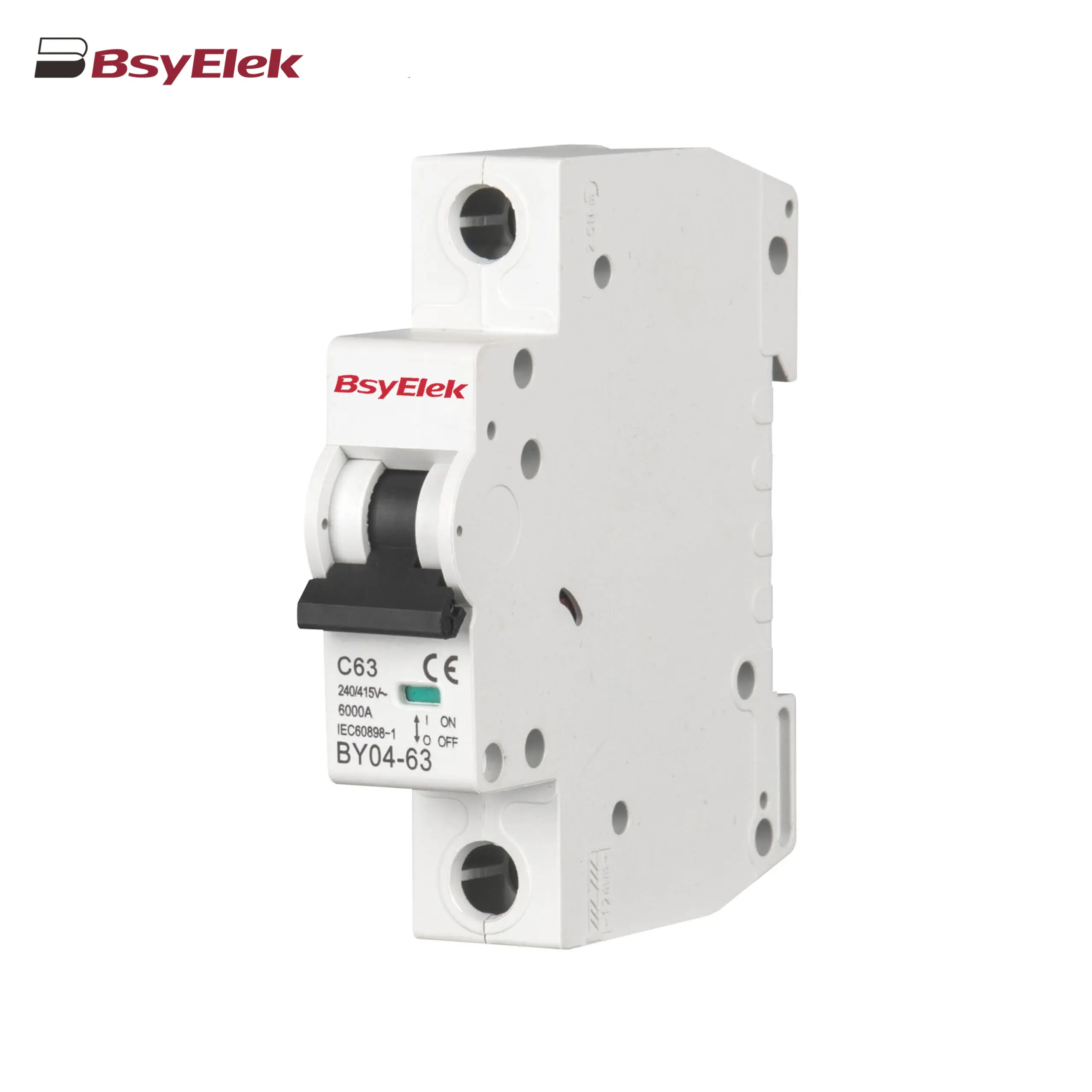
BY04-63 MCB 6-10KA Miniature Circuit Breaker
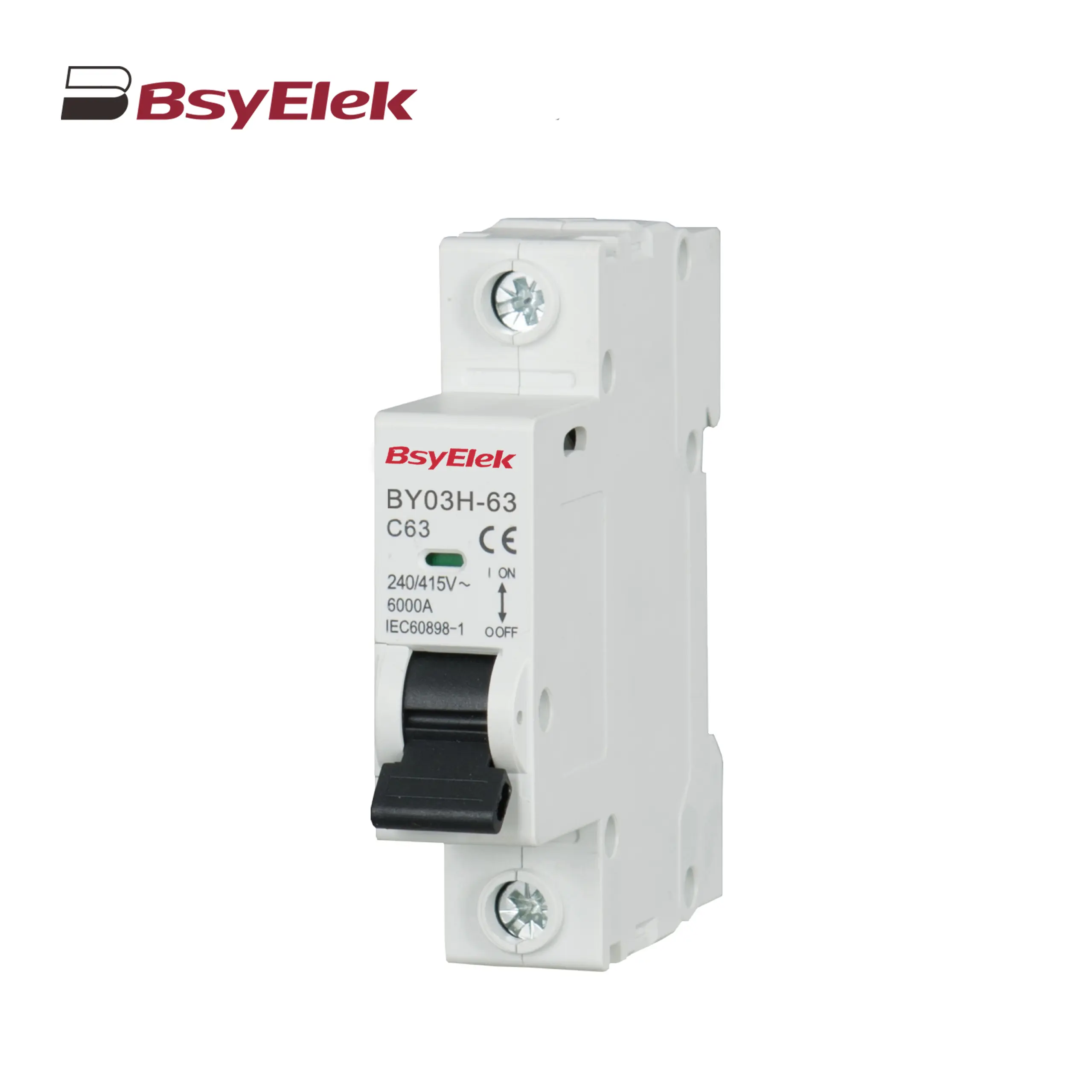
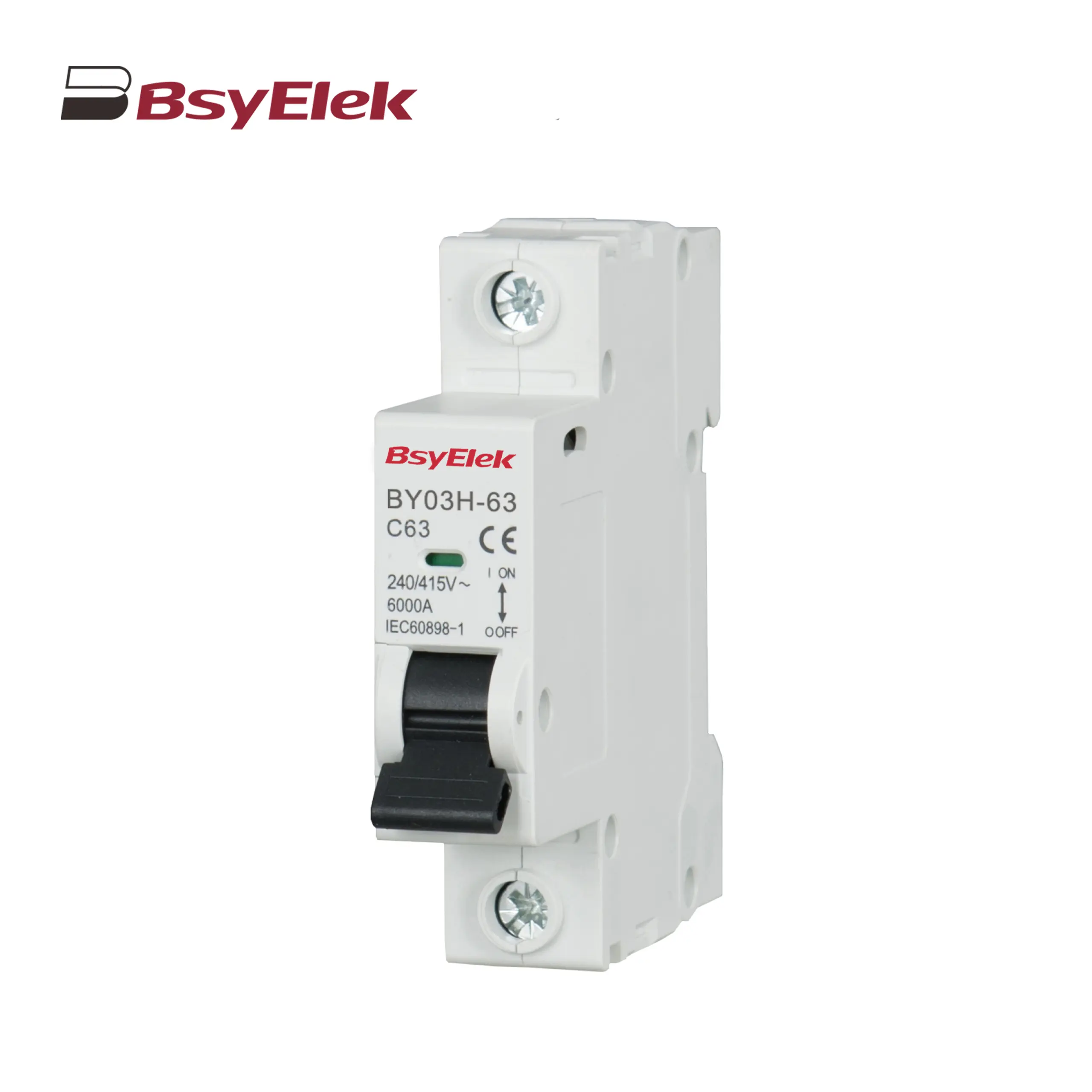
BY03H-63 MCB 6KA Miniature Circuit Breaker
BY03-63 MCB 4.5KA Miniature Circuit Breaker
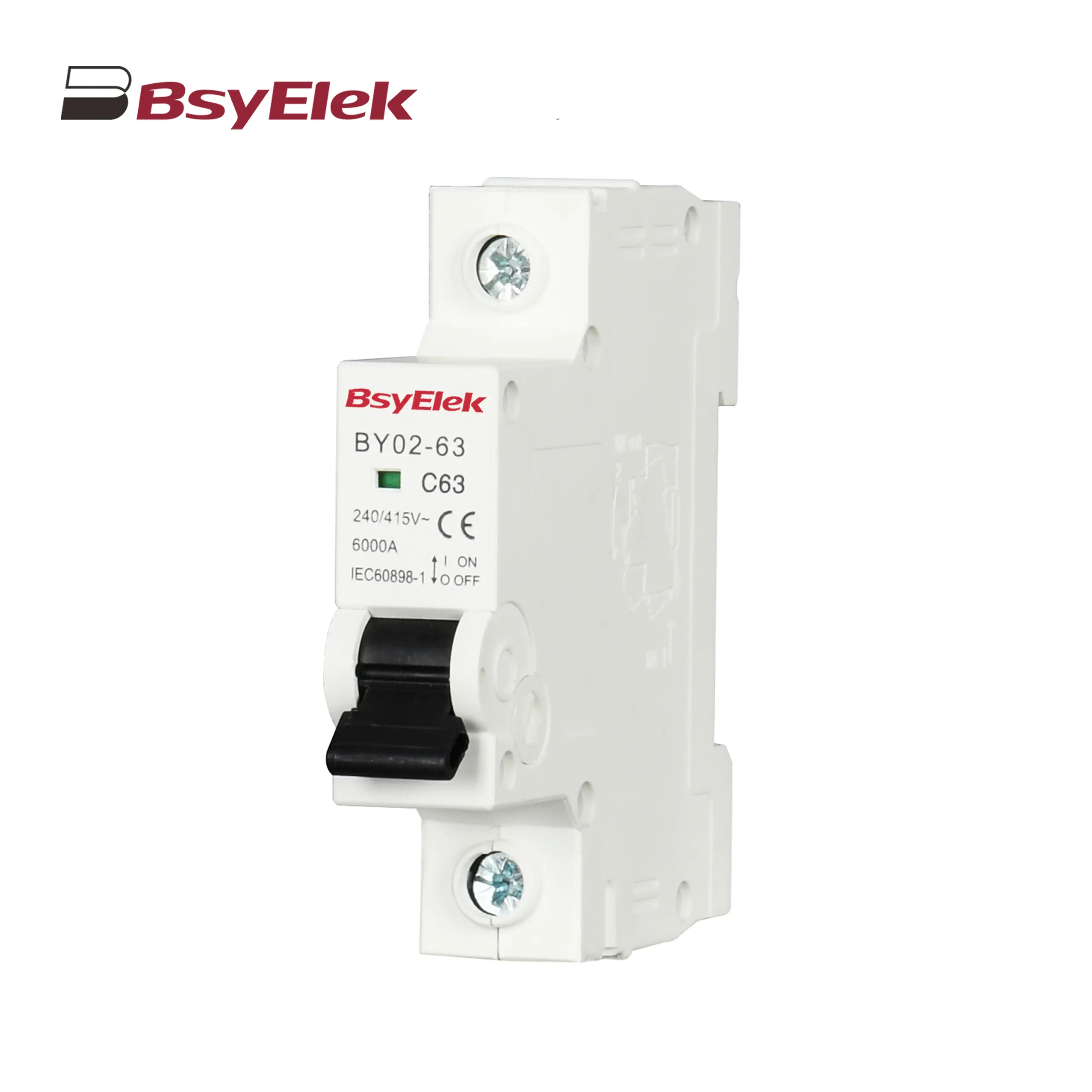
BY02-63 MCB 3kA Miniature Circuit Breaker
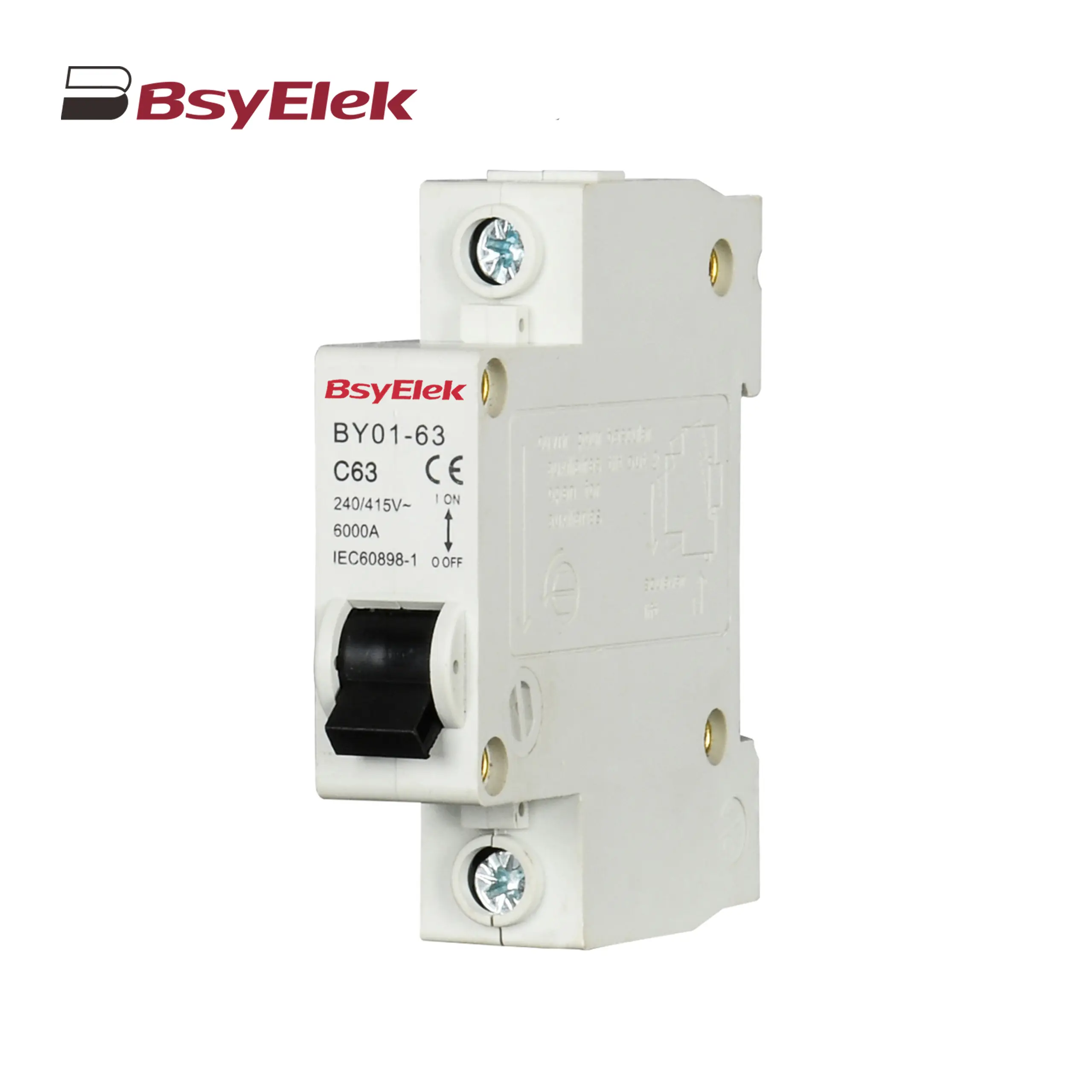
BY01-63 MCB 3kA Miniature Circuit Breaker
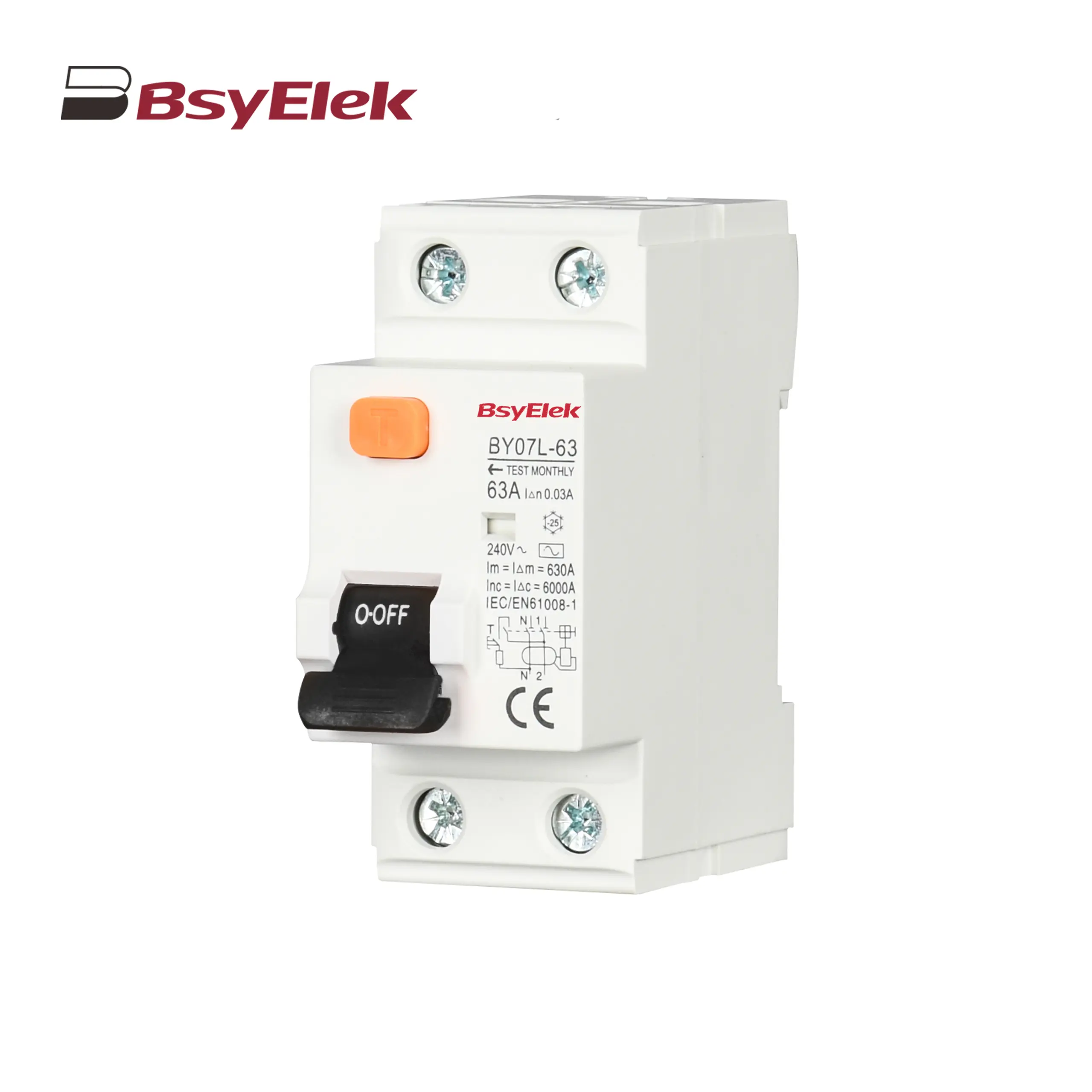
BY07L-63 RCCB 6KA Residual Current Circuit Breaker
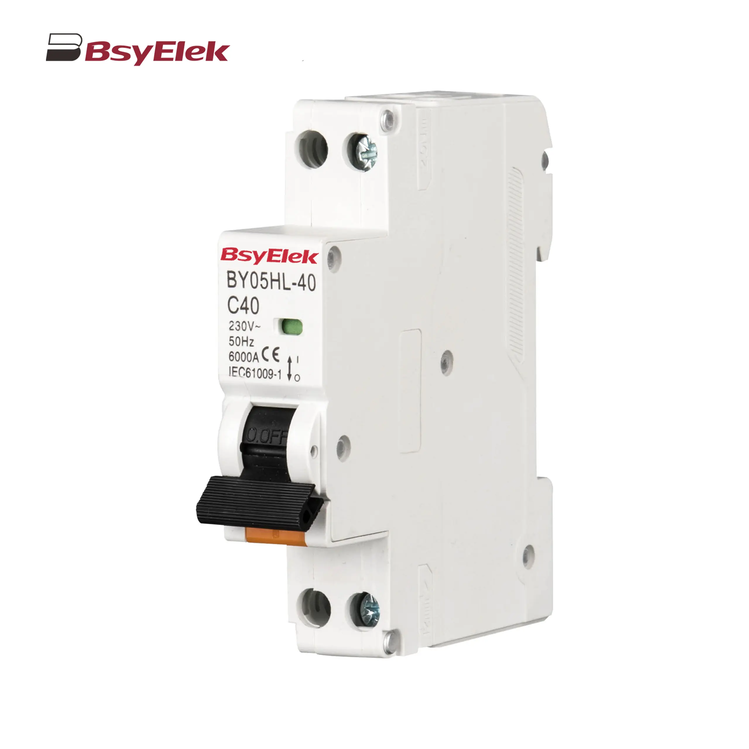
BY05HL-40 RCBO 6KA Residual Current Circuit Breaker with Over-current Protection
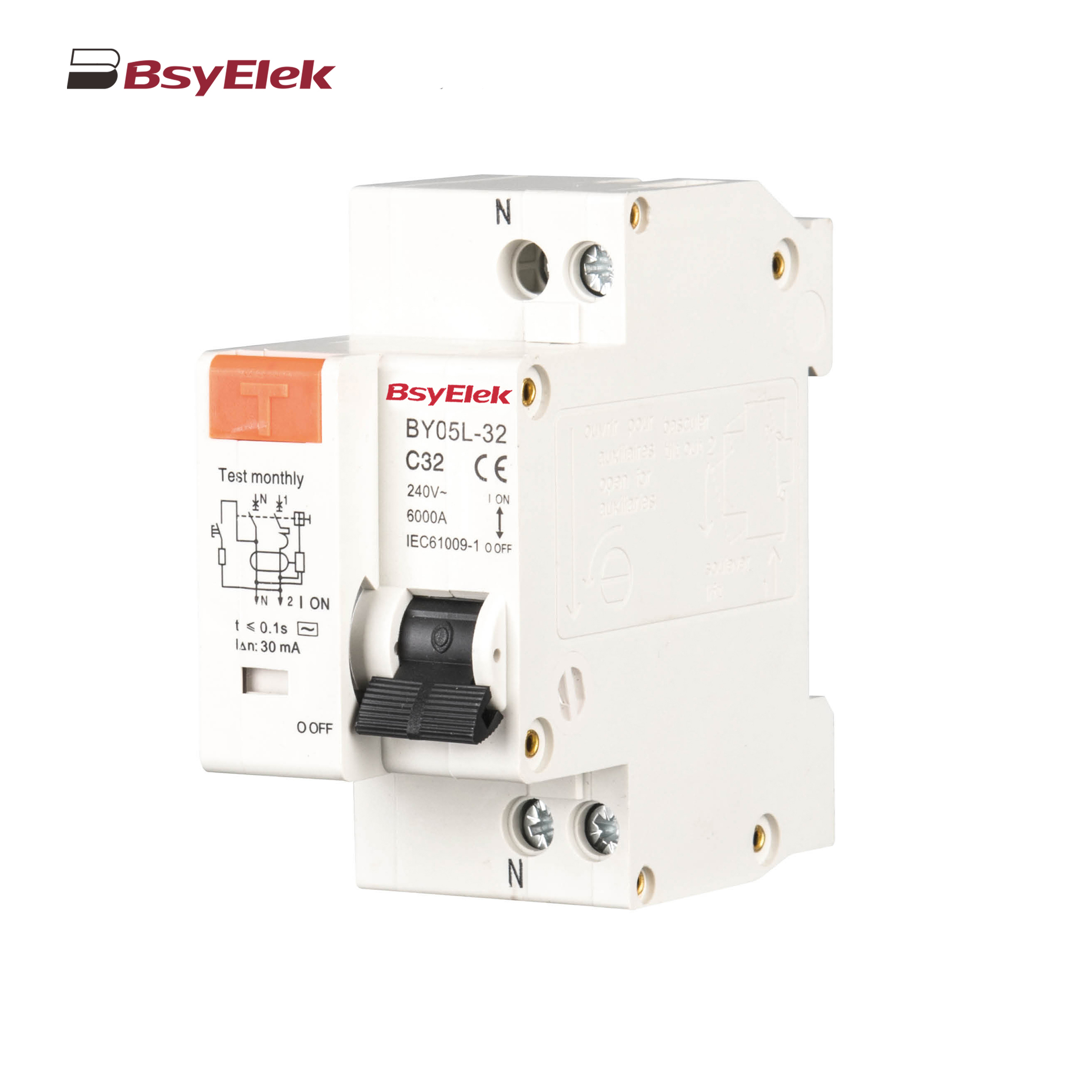
BY05L-32 RCBO 3KA Residual Current Circuit Breaker with Over-current Protection
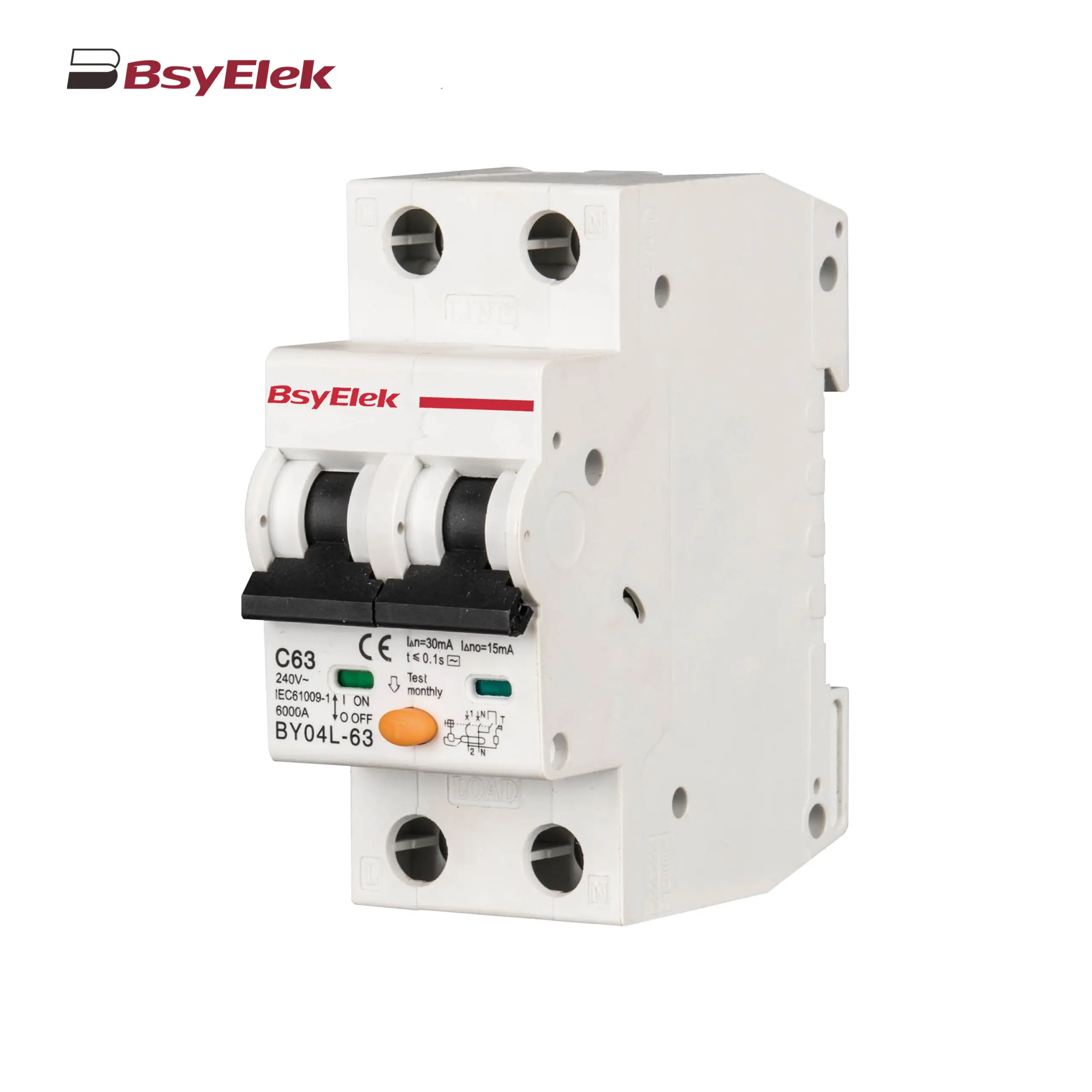
BY04L-63 RCBO 6KA Residual Current Circuit Breaker with Over-current Protection
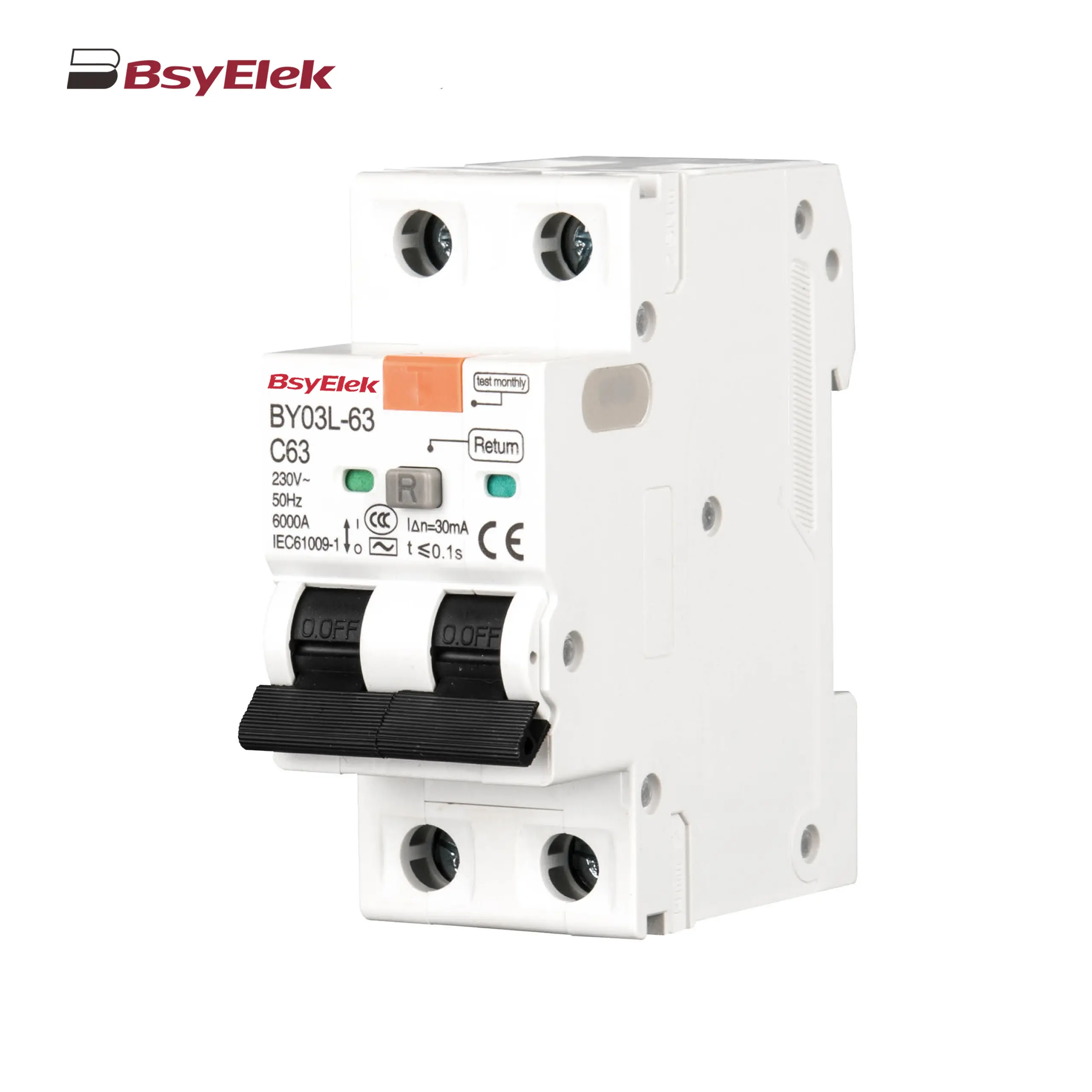
BY03L-63 RCBO 4.5KA Residual Current Circuit Breaker with Over-current Protection
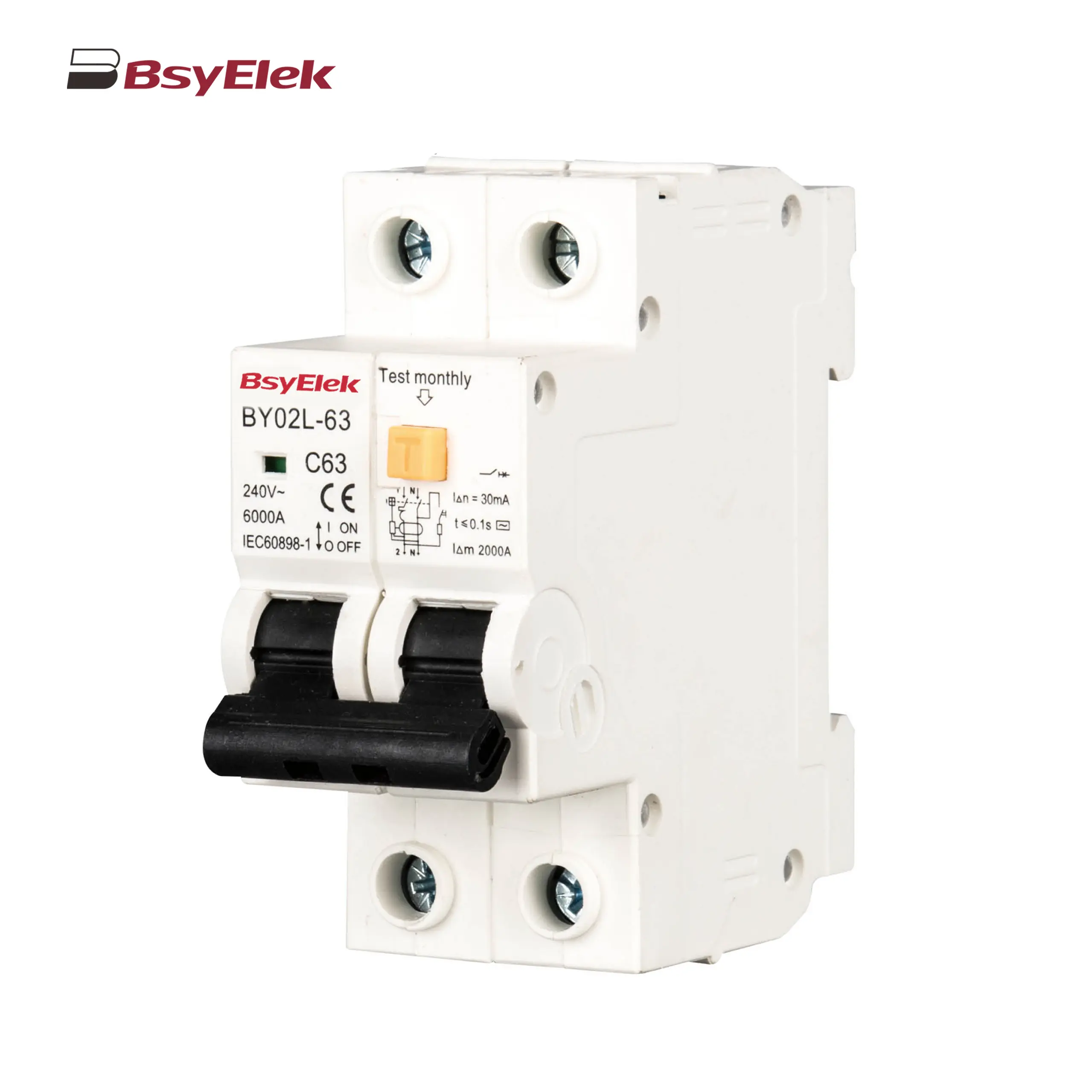
BY02L-63 RCBO 3KA Residual Current Circuit Breaker with Over-current Protection
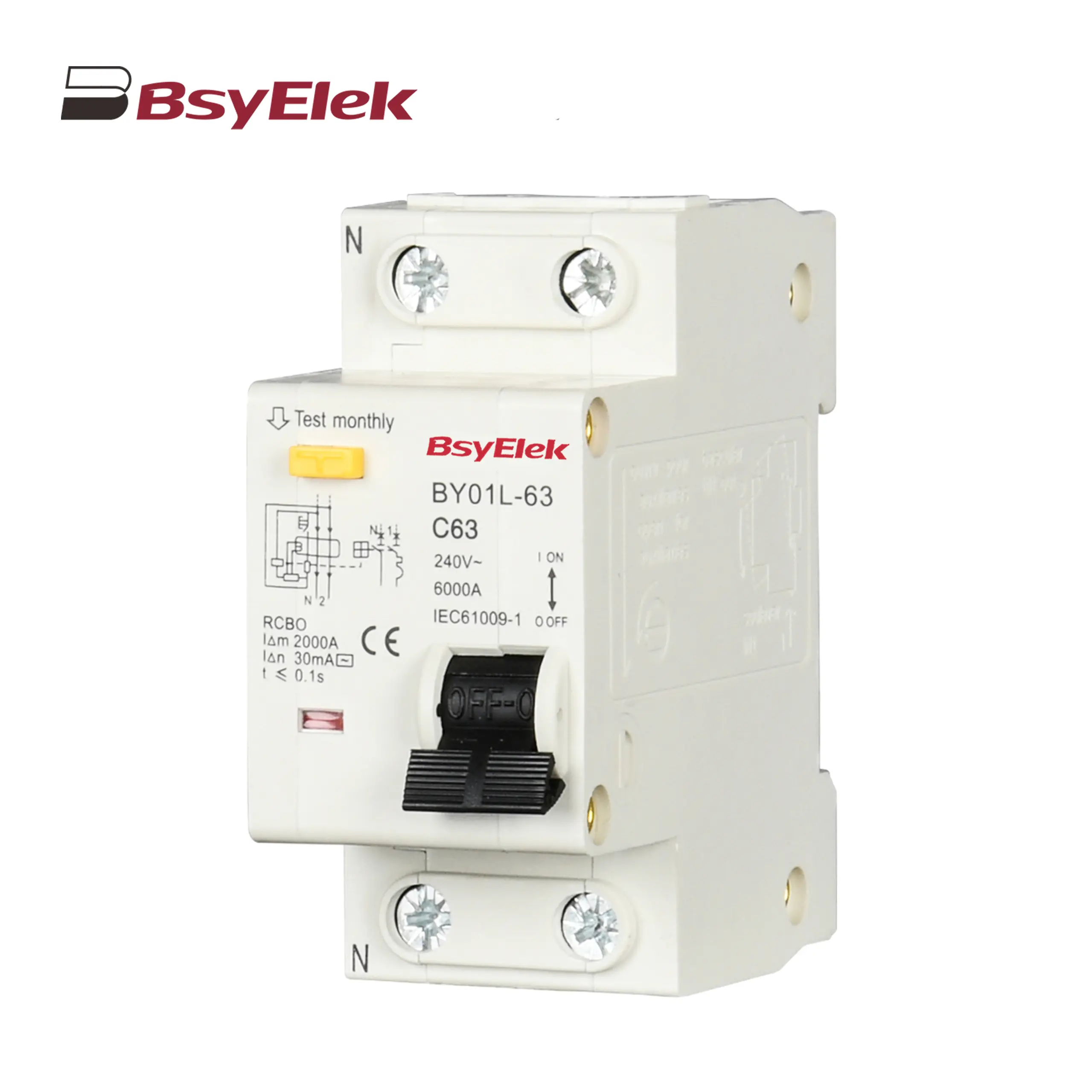
BY01L-63 RCBO 1P+N 3KA Residual Current Circuit Breaker with Over-current Protection
BY06H-125DC MCB 10-15kA DC Miniature Circuit Breaker
BY06-125DC MCB 6kA DC Miniature Circuit Breaker
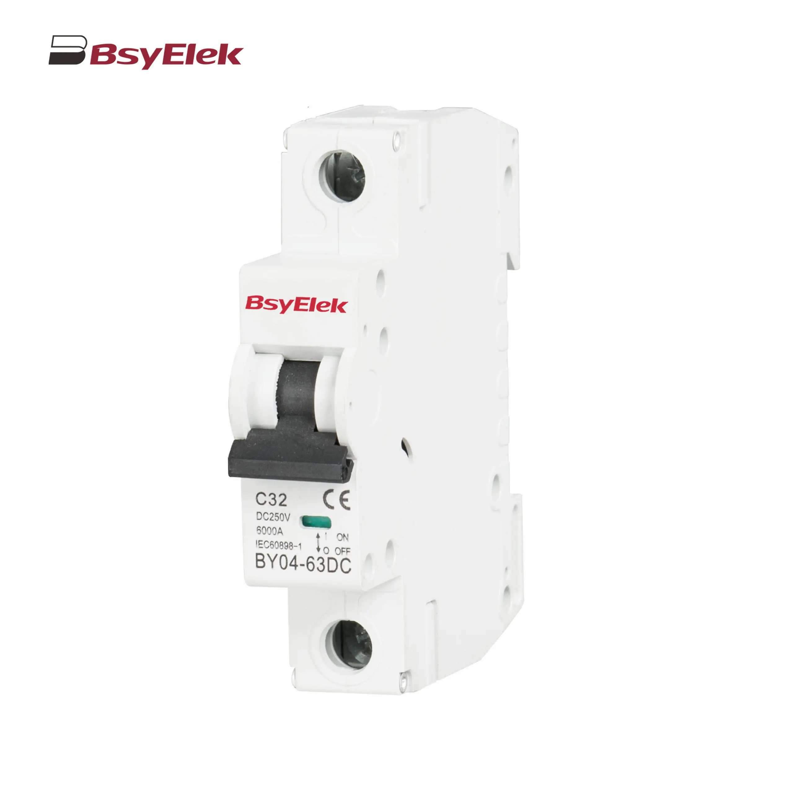
BY04-63DC MCB 6-10kA DC Miniature Circuit Breaker
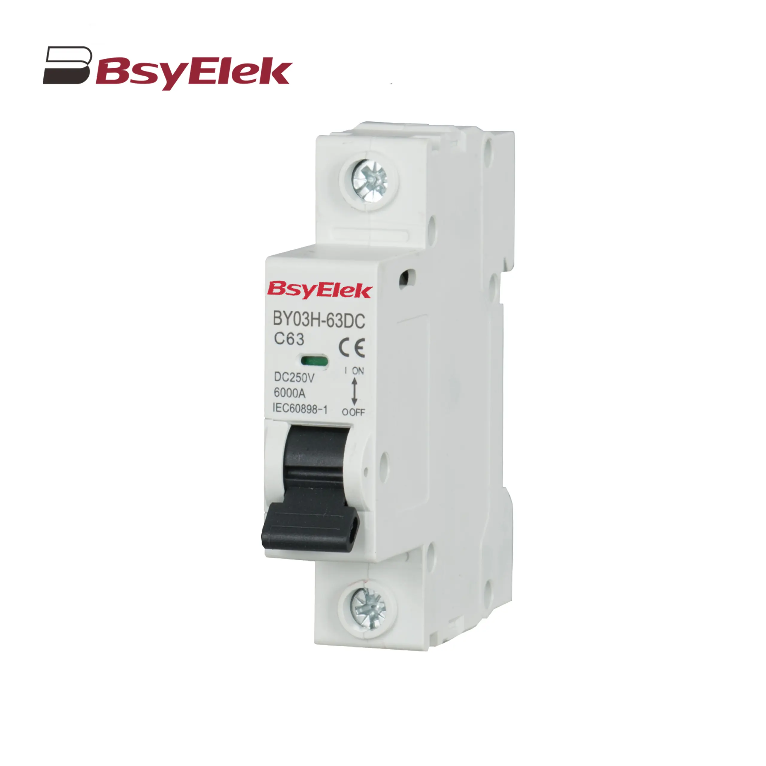
BY03H-63DC MCB 6kA DC Miniature Circuit Breaker
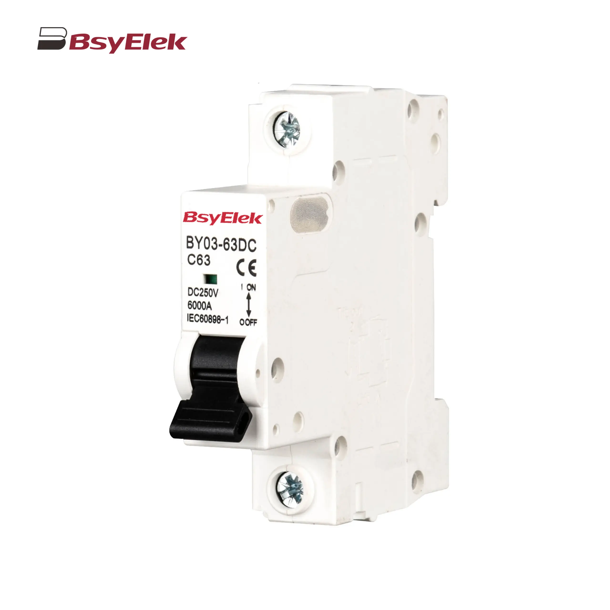
BY03-63DC MCB 4.5kA DC Miniature Circuit Breaker
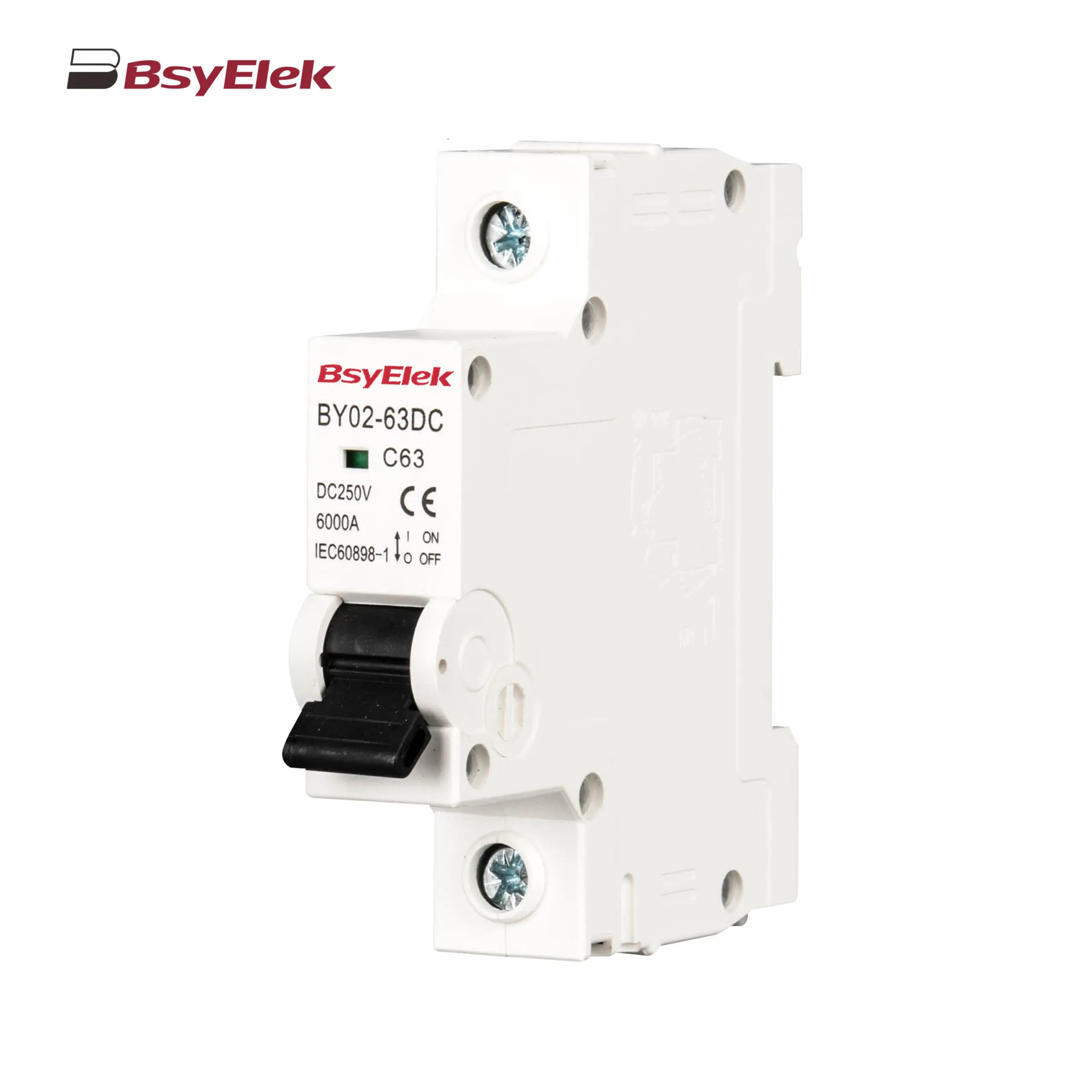
BY02-63DC MCB 3kA DC Miniature Circuit Breaker
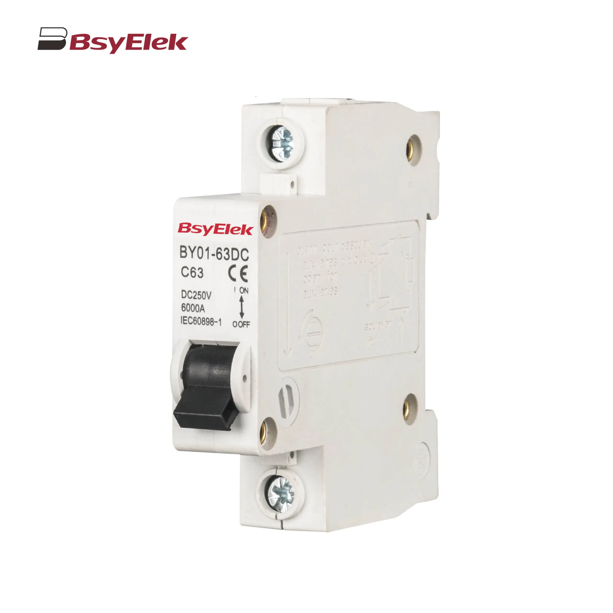
BY01-63DC MCB 3kA DC Miniature Circuit Breaker
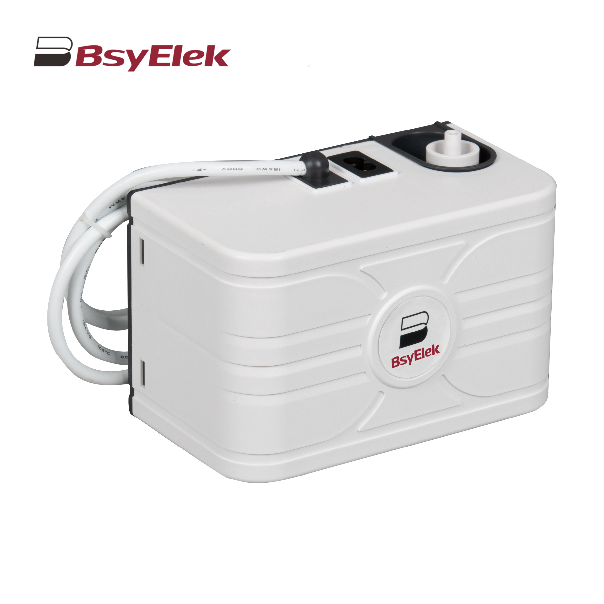
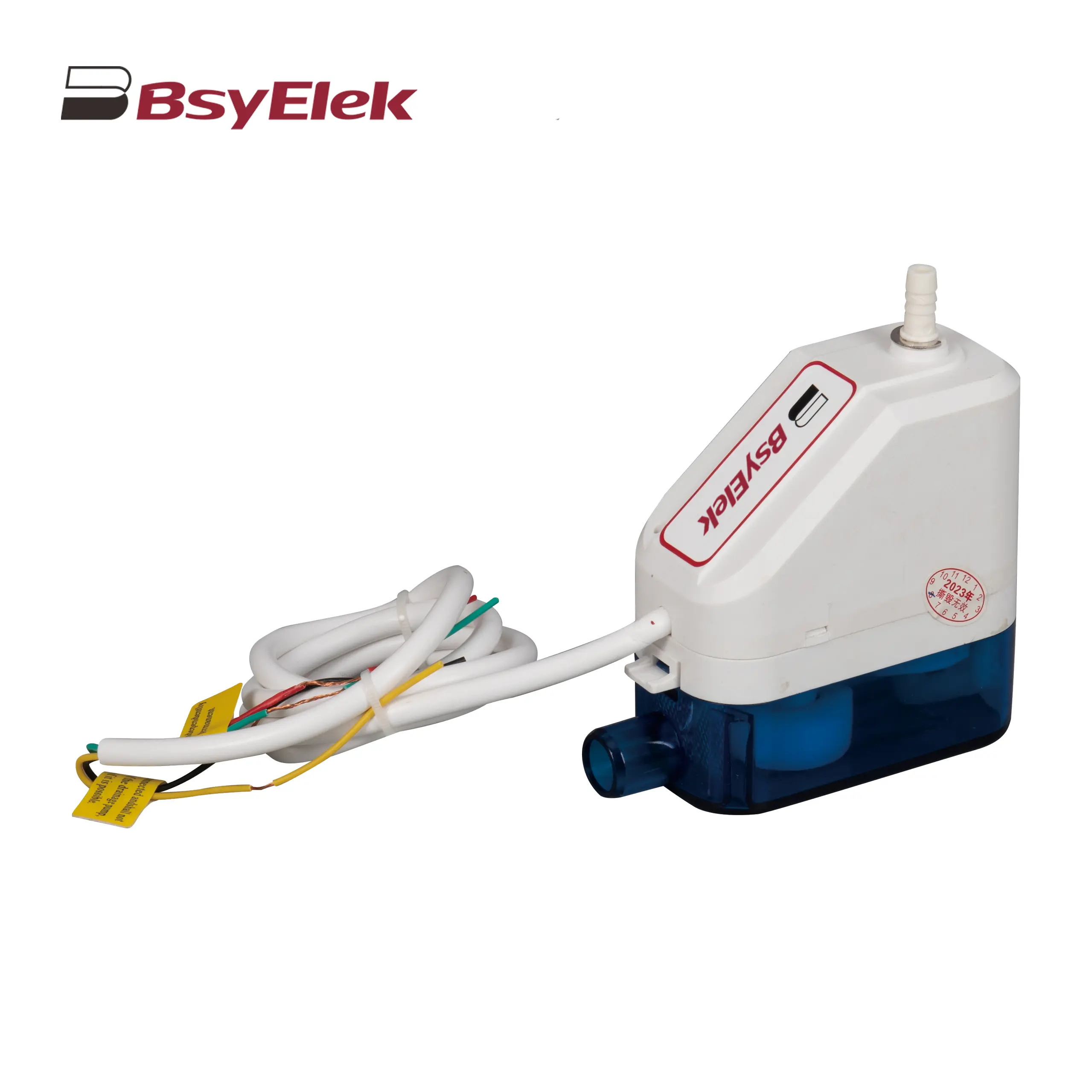
BY-5018 1.8M Engineering Drainage Pump
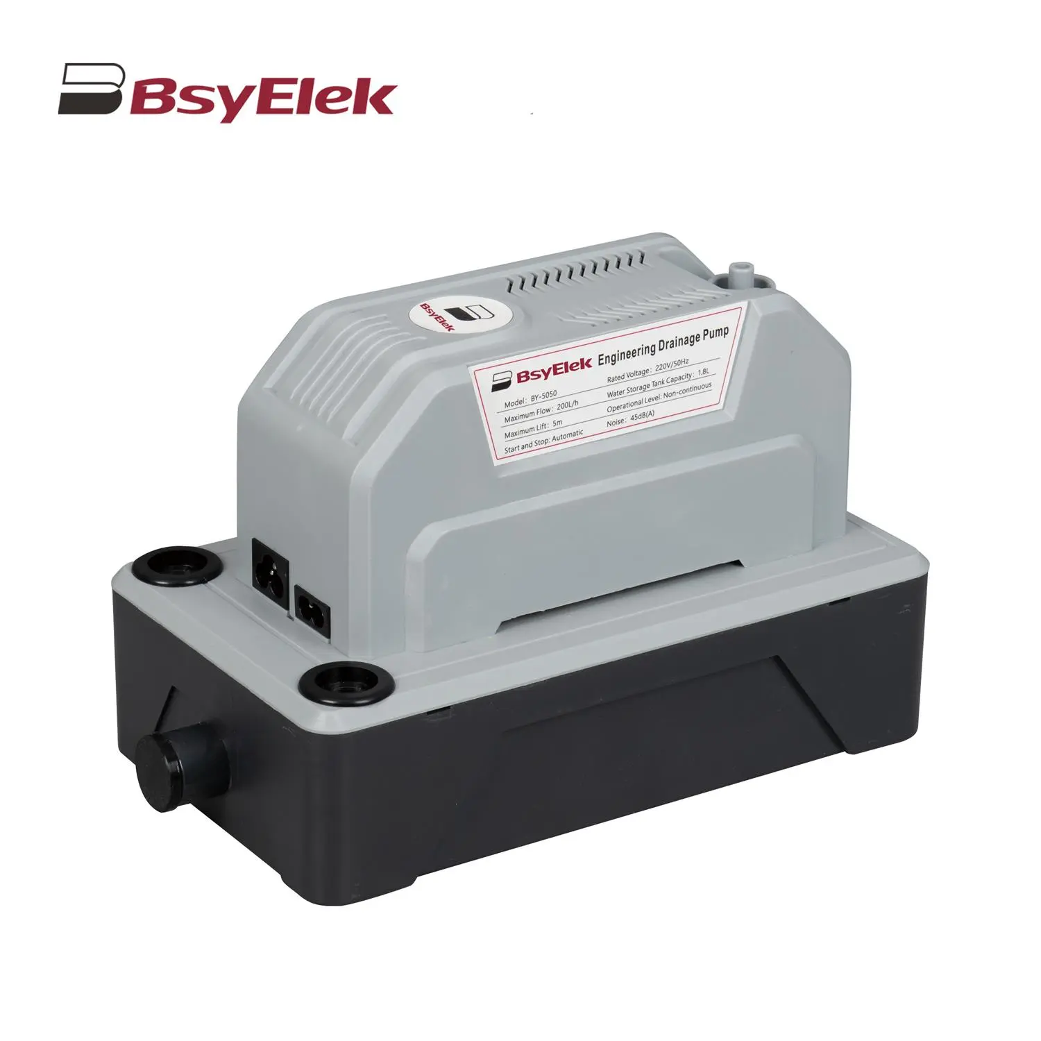
BY-5050 5M Engineering Drainage Pump
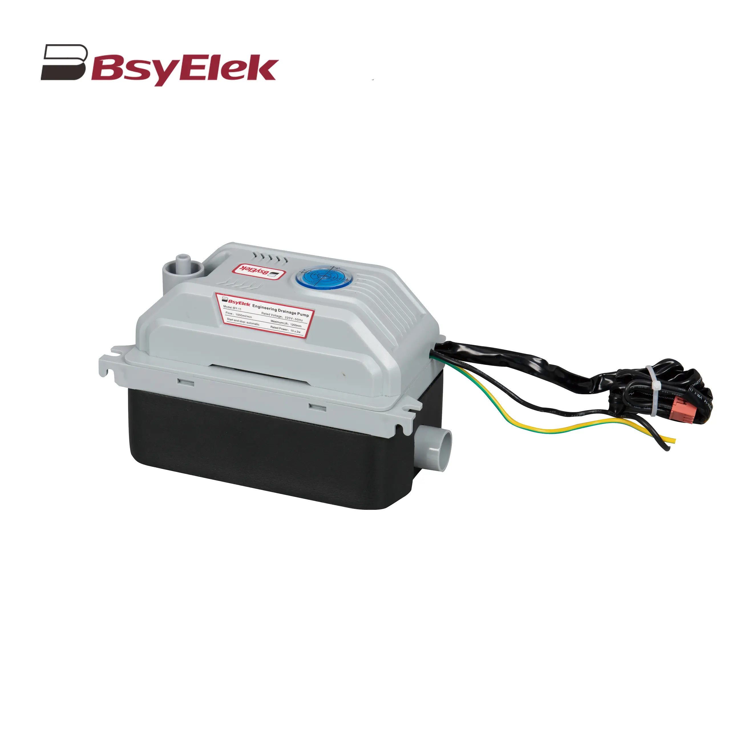
BY-11 1.2M Engineering Drainage Pump
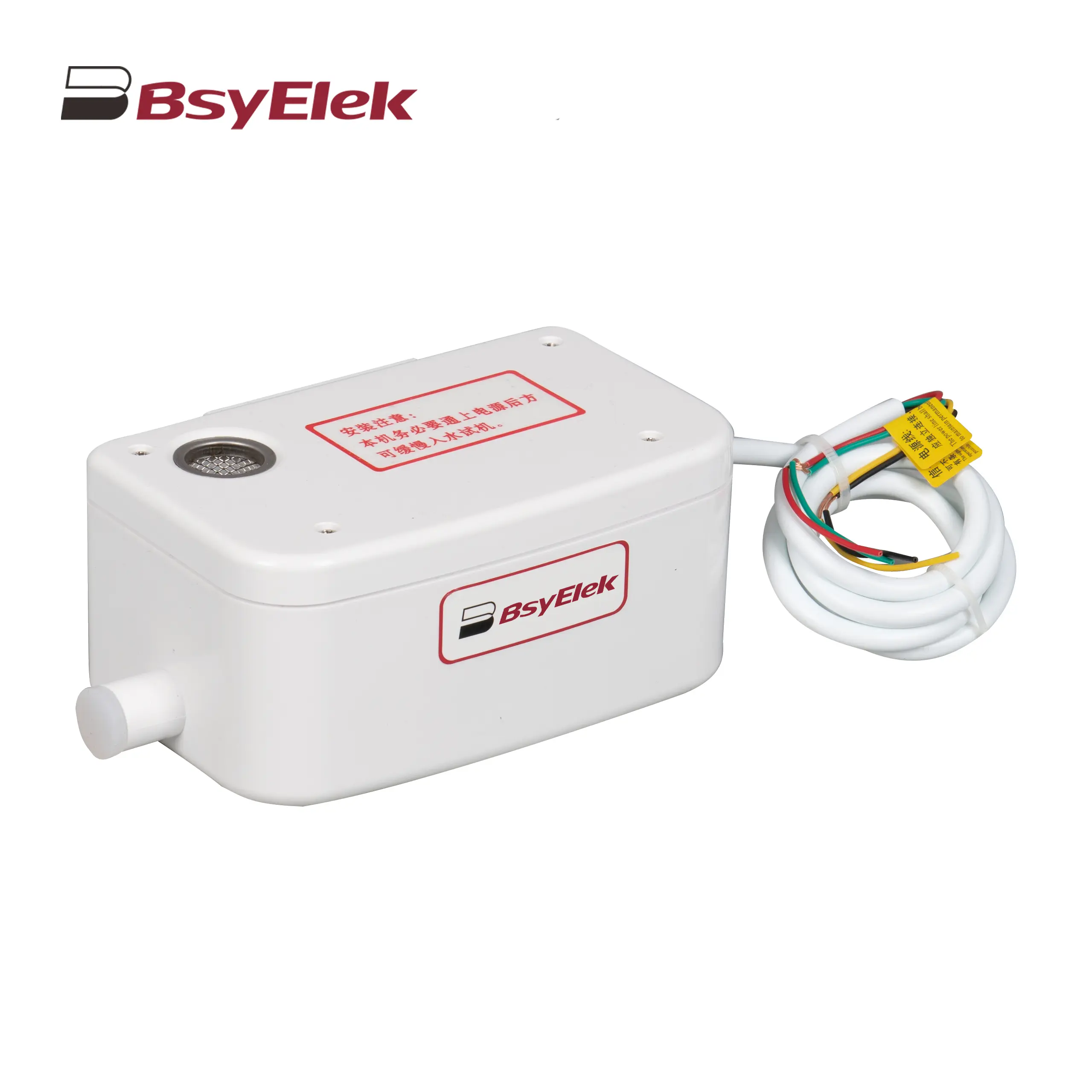
SBH-05 0.7M Original Drainage Pump of Duct Type Air Conditioner
BY-24A/40A 10M Drainage Pump of Air Conditioner
BY-50A 12M Drainage Pump of Air Conditioner
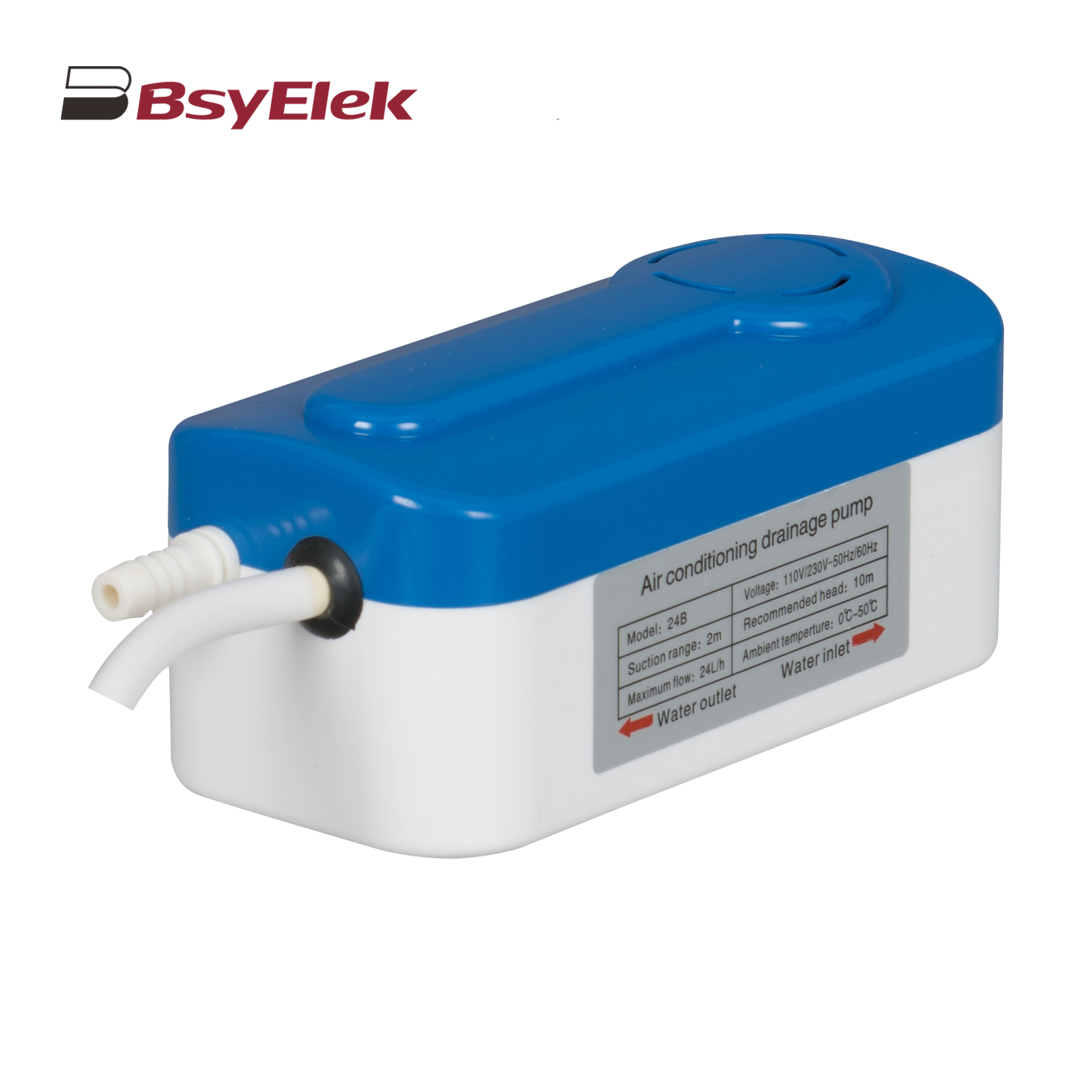
BY-24B/40B 10M Split Type Drainage Pump
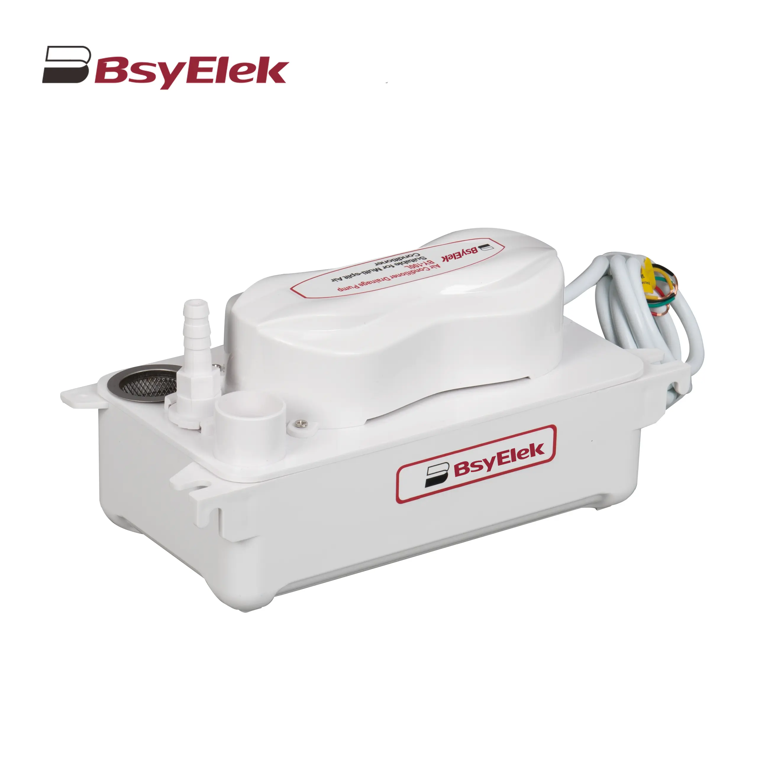
BY-100L 2M Drainage Pump of Air Conditioner
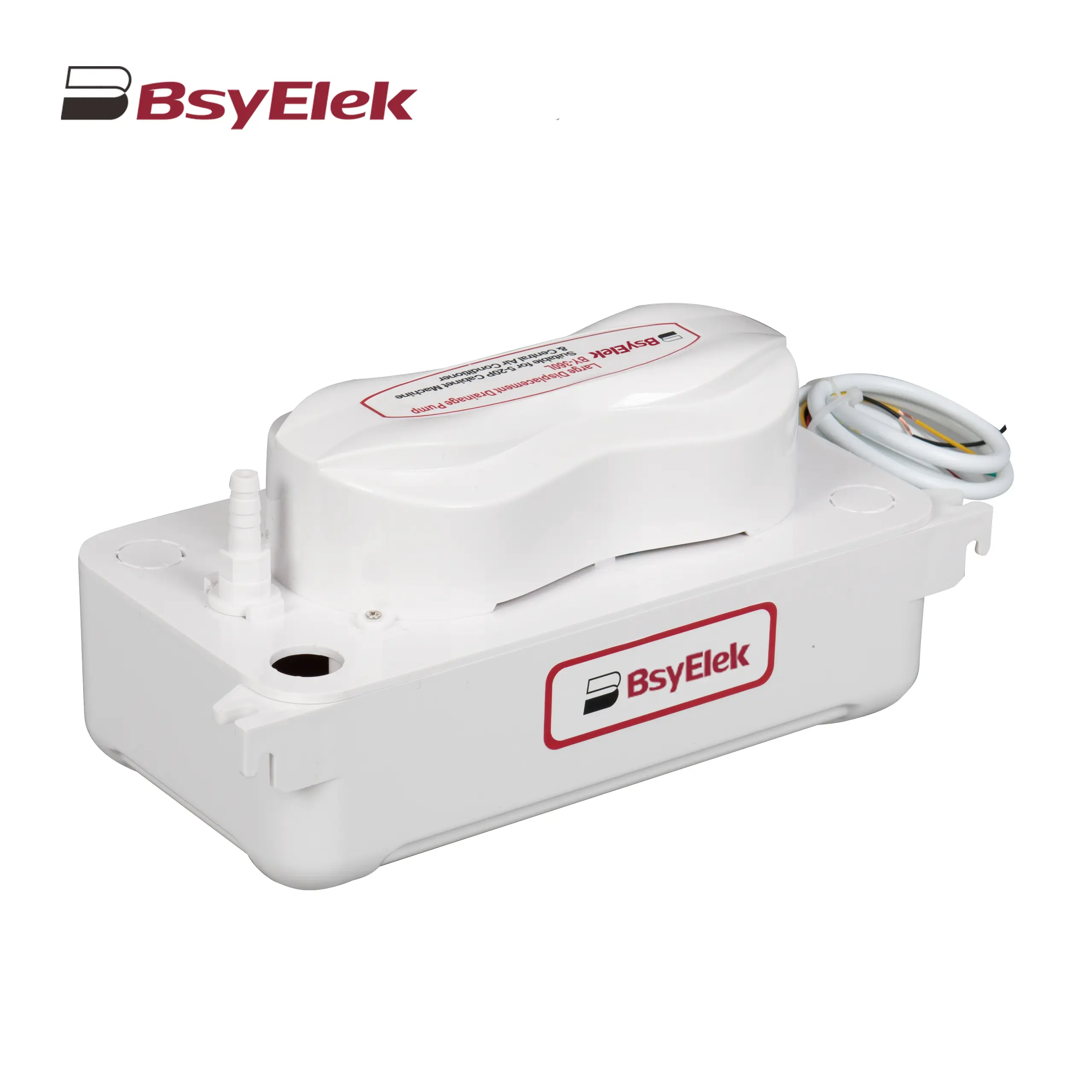
BY-360L 6M Large Displacement Drainage Pump
BY-24C/40C 10M Corner Drainage Pump
Choosing the right Disconnect Switch is a practical decision, not a simple catalog exercise. The device must isolate equipment safely, match the circuit, and withstand its operating environment. A workshop panel, rooftop HVAC unit, and industrial motor need different solutions.
Hugh Hoagland, a recognized electrical-safety expert, has said, “An arc flash is an electrical explosion.” That warning gives this topic real weight. A properly selected switch can create visible isolation, support maintenance procedures, and reduce avoidable exposure to energized parts. However, it cannot replace lockout/tagout practices, training, or verified de-energization.
This guide examines the top types of Disconnect Switches, including fusible, non-fusible, enclosed, rotary, and safety switches. Each type offers a different balance of protection, switching capacity, installation space, and maintenance convenience. Fusible models add overcurrent protection. Non-fusible models usually provide isolation without replacing upstream protection. Rotary switches suit compact control panels. Enclosed switches protect internal components from dust, moisture, and accidental contact.
The details matter. Check voltage, current, poles, short-circuit ratings, enclosure ratings, and local standards. A switch that fits physically may still be electrically unsuitable. That mistake is easy to make.
Even experienced teams can overlook starting current or harsh outdoor conditions. I would not treat product labels as complete engineering decisions. The safest choice comes from comparing the application, the equipment manual, and applicable IEC or UL requirements. This article provides a clear starting point, while qualified professionals should confirm final selections.
A disconnect switch is a mechanical device that separates electrical conductors from a power source. It creates a visible isolation point for maintenance, inspection, or emergency control. When the handle moves to OFF, internal contacts open and interrupt the circuit. The enclosure then helps protect users from exposed live parts, dust, moisture, and accidental contact. It does not always provide overload protection.
The main types include fusible, non-fusible, enclosed, and switch-disconnector designs. A fusible disconnect combines circuit isolation with replaceable fuses. A non-fusible model isolates power but requires separate overcurrent protection. Switch-disconnectors are designed to interrupt specified load currents under defined conditions. IEC 60947-3 sets performance requirements for many switch-disconnector applications. In the United States, the Bureau of Labor Statistics’ 2023 Census of Fatal Occupational Injuries recorded more than 100 fatal incidents involving exposure to electricity. That figure shows why isolation cannot depend on appearance alone.
A proper installation matches voltage, current, fault ratings, enclosure rating, and switching duty. Indoor equipment may need basic protection, while washdown areas require stronger environmental protection. A field inspection should confirm clear labeling and accessible operation. Lockout and verification remain essential. A switch can look simple. That is where mistakes begin. Even experienced technicians may misread a shared supply, an alternate source, or a backfeed path. NFPA 70E emphasizes electrically safe work practices, including de-energizing and verifying the absence of voltage before qualified work begins.
Representative rated-voltage bands commonly found in low-voltage disconnect equipment
A disconnect switch provides a visible means of isolating electrical equipment from its power source for servicing and safety. Fusible disconnects combine isolation with overcurrent protection, while non-fusible switches provide isolation without built-in fuses. Switch-disconnectors are designed to interrupt current when properly rated, and DC disconnects require ratings specifically tested for direct-current arcs. The voltage bands shown are representative ranges, not universal limits for every installation.
What Are the Main Types of Disconnect Switches?
Disconnect switches isolate electrical equipment for maintenance, inspection, or emergency control. Their design depends on voltage, current, enclosure location, and switching frequency. The main types include fusible, non-fusible, load-break, and enclosed safety disconnects.
A fusible disconnect combines isolation with overcurrent protection. It can limit damage when a short circuit occurs, but replacement requires correctly rated fuses. A non-fusible disconnect provides isolation without built-in overcurrent protection. It works well where upstream protection already exists. Load-break switches can interrupt current during normal operation. Ordinary isolators may not safely interrupt energized loads. Rotary and lever-operated designs are common in industrial panels because operators can see their position clearly.
IEC 60947-3 covers switch-disconnectors, disconnectors, and fuse-combination units. Its testing framework addresses switching performance and electrical endurance. The IEA Electricity 2024 report projects average global electricity-demand growth of about 4% annually from 2024 through 2026. That expansion increases pressure on dependable isolation in buildings, factories, and renewable-energy installations. Still, choosing only by amperage is a weak practice. Fault ratings, pole configuration, enclosure protection, and ambient temperature also matter.
Tips: Check the available fault current before selecting a switch. Confirm whether the device must interrupt a loaded circuit. Use a lockable handle where servicing requires controlled isolation. In damp or dusty areas, specify a suitable enclosure rating. Field labels should match the actual circuit, not an old drawing. A second review is worthwhile; installation assumptions are often wrong.
Fusible and non-fusible disconnect switches serve different electrical purposes. A fusible disconnect contains fuses that interrupt excessive current during a fault. This extra protection can help prevent overheated conductors, damaged equipment, and electrical fires. In a workshop, for example, a correctly sized fuse may open when a motor develops a serious internal fault.
A non-fusible disconnect provides a visible means to isolate power, but it does not provide overcurrent protection. The circuit therefore needs a properly rated fuse or circuit breaker elsewhere. These switches often suit equipment that already has coordinated protection upstream. During field inspections, technicians check voltage, current, enclosure rating, conductor size, and available fault current. Choosing only by ampere rating is a common mistake. Real installations are less forgiving than catalogs suggest.
Tips: Match the switch to the load and environment. Use a fusible model when the equipment requires local overcurrent protection. Select a non-fusible model when protection is already correctly installed. Verify the fuse class, disconnect rating, and short-circuit rating before installation. Keep the enclosure accessible and clearly labeled. Cut power first. A qualified electrician should confirm the design against applicable electrical codes, especially for motors, outdoor equipment, and damp locations.
Choosing a disconnect switch starts with the application, not the catalog picture. A fused disconnect suits circuits needing clear overcurrent protection, such as motors, pumps, and outdoor equipment. Its fuse rating must match the conductor and load. A non-fused switch works well when upstream protection already exists. It provides visible isolation without adding another protective device.
For machinery near dust, moisture, or accidental contact, an enclosed disconnect offers practical protection. NEMA or IP ratings should match the environment. A rotary disconnect fits compact panels and gives a clear on-off position. It is useful for service technicians working beside conveyors, compressors, or packaging equipment. A safety switch with a lockable handle supports controlled maintenance. The lock matters when several workers share one machine.
High-current installations may require a heavy-duty enclosed design with suitable short-circuit ratings. Solar arrays, HVAC systems, and industrial feeders can demand different pole counts and switching methods. Always verify voltage, current, frequency, enclosure material, and terminal capacity. Local electrical requirements still control the final choice.
A clean installation can still be unsuitable. I have seen disconnects mounted where water reached the cable entry. The switch was correctly rated, but the installation was not. That detail is easy to miss. Engineers should also check operating temperature, available fault current, and access clearance before approval. When uncertain, consult a qualified electrician and the equipment documentation.
| Disconnect Switch Type | Operating Mechanism | Typical Voltage Range | Typical Current Range | Primary Protection or Function | Best-Suited Applications | Main Advantages | Important Selection Considerations |
|---|---|---|---|---|---|---|---|
| Fusible Disconnect Switch | A manually operated switch connected in series with replaceable fuses. | Up to approximately 1,000 V AC or DC, depending on the design and applicable standard. | Commonly 30–1,200 A; larger ratings are available in industrial switchgear. | Provides visible isolation and short-circuit and overcurrent protection when correctly fitted with suitable fuses. | Motor circuits, feeders, transformers, commercial distribution panels, and photovoltaic systems. | Combines circuit isolation with overcurrent protection; fuse replacement is straightforward. | Fuse class, interrupting rating, available fault current, heat dissipation, and spare-fuse requirements must be checked. |
| Non-Fusible Disconnect Switch | Manually opens and closes the circuit without an integral fuse. | Commonly 240–1,000 V AC; some designs are rated for DC systems. | Commonly 30–1,200 A, with higher ratings available for industrial equipment. | Provides isolation and local switching but does not normally provide overcurrent protection by itself. | Equipment isolation, HVAC units, machinery, pumps, and circuits already protected by an upstream device. | Simple construction, lower maintenance, and convenient local means of disconnecting equipment. | Verify that upstream circuit protection is correctly sized and that the switch has the required short-circuit and utilization ratings. |
| Enclosed Safety Switch | A fusible or non-fusible switch installed inside a protective enclosure with an external operating handle. | Commonly 240–600 V AC; specialized enclosures may support higher system voltages. | Typically 30–1,200 A. | Provides switching and isolation while protecting internal live parts from accidental contact, dust, and moisture. | Outdoor equipment, industrial machinery, workshops, rooftop units, and wet or dusty locations. | Improves personnel safety and environmental protection; many versions support lockout procedures. | Select the enclosure rating, corrosion resistance, grounding arrangement, padlock provisions, and installation environment. |
| Rotary Disconnect Switch | A rotating handle drives contacts through a compact cam or rotary contact mechanism. | Commonly 250–1,000 V AC or DC, depending on pole configuration and product design. | Often 16–160 A; higher-current versions are available. | Provides manual isolation and load switching; overcurrent protection is usually supplied separately. | Control panels, machine tools, packaging equipment, small motors, battery systems, and automation equipment. | Compact footprint, clear ON/OFF indication, multiple-pole switching, and convenient panel mounting. | Check utilization category, DC switching capability, number of poles, handle position, and short-circuit withstand rating. |
| Knife-Blade Disconnect Switch | Exposed or enclosed hinged blades physically separate from fixed contacts. | Commonly used on low-voltage AC and DC systems; rating depends strongly on the enclosure and construction. | From low-current laboratory equipment to several hundred amperes in industrial applications. | Primarily provides visible isolation; separate fuses or circuit breakers are generally required for fault protection. | Industrial distribution, test equipment, battery banks, maintenance isolation, and applications requiring a visible open position. | Clear physical indication of contact separation and a simple, easily understood mechanism. | Evaluate arc control, touch protection, enclosure design, load-switching capability, and suitability for energized switching. |
| Transfer or Double-Throw Disconnect Switch | Routes a load between two sources or positions, such as normal and standby power. | Commonly 240–600 V AC; higher-voltage versions are used in specialized systems. | Commonly 30–1,200 A. | Provides source selection and, in suitable designs, prevents simultaneous connection of two sources. | Generator transfer, emergency power, dual-source machinery, and maintenance bypass arrangements. | Supports controlled source changeover and can provide mechanical interlocking. | Confirm pole configuration, switching sequence, neutral switching requirements, break-before-make operation, and standby-source compatibility. |
| DC Battery Disconnect Switch | Uses specially designed contacts, magnets, or arc-extinguishing features to interrupt direct current. | Commonly 12–1,000 V DC, depending on the number of poles and series arrangement. | Typically 50–600 A; higher ratings are available for energy-storage and industrial systems. | Provides battery isolation and may be combined with fuse protection or a battery-management system. | Uninterruptible power supplies, electric vehicles, energy-storage systems, telecom power, and industrial battery banks. | Designed for DC arc control and rapid isolation of stored electrical energy. | Verify DC voltage, continuous and interrupting current, polarity, pre-charge requirements, arc suppression, and available fault current. |
| Draw-Out or Withdrawable Disconnect | A removable switching or circuit-protection unit physically disconnects from stationary primary contacts. | Commonly used in low-voltage and medium-voltage switchgear systems. | From several hundred amperes to several thousand amperes. | Provides isolation, access for maintenance, and may incorporate circuit interruption and interlocking functions. | Large commercial buildings, manufacturing plants, data centers, utility distribution, and critical power systems. | Allows faster maintenance and equipment replacement while keeping the main enclosure in place. | Consider arc-flash procedures, position interlocks, racking mechanisms, grounding shutters, maintenance clearance, and switchgear compatibility. |
| Typical ranges are general industry values rather than universal limits. Final selection should be based on system voltage, continuous current, fault current, load type, AC or DC operation, enclosure conditions, local electrical codes, and the applicable product standard. | |||||||
Selecting a disconnect switch starts with the equipment, not the product label. Start with the load. Check the system voltage, operating current, frequency, and available fault current. A fused disconnect can provide overcurrent protection, while a non-fused version mainly provides isolation. Rotary switches suit compact control panels. Enclosed switches work better where dust, moisture, or accidental contact is possible.
The number of poles also matters. Single-phase equipment may need two poles, while three-phase machinery commonly requires three or four poles. Confirm whether the circuit is AC or DC, because switching performance can differ greatly. The switch must handle the motor’s starting current, not only its nameplate running current. A small mismatch can create heat, nuisance trips, or shortened service life.
Look at the installation environment closely. Outdoor equipment may require a weather-resistant enclosure, UV protection, and suitable corrosion resistance. Check terminal size, cable entry space, padlock provisions, and the required isolation position. Verify the applicable electrical standards and the manufacturer’s tested ratings. A practical mistake is choosing by amperage alone. That sounds simple, but it misses fault rating and enclosure conditions. Ask one more question: can an electrician safely inspect and operate it while wearing gloves? If the answer feels uncertain, the selection needs another review.