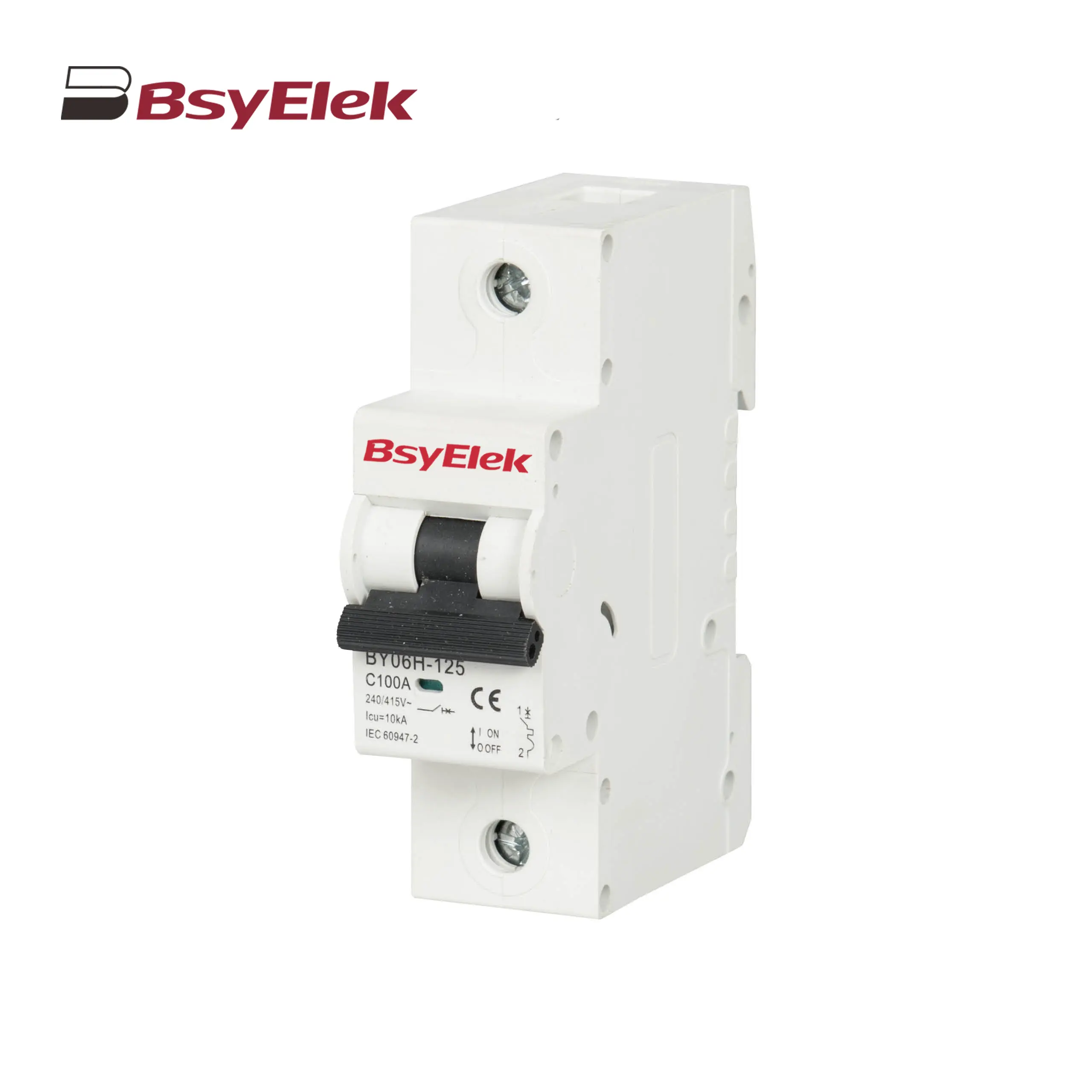
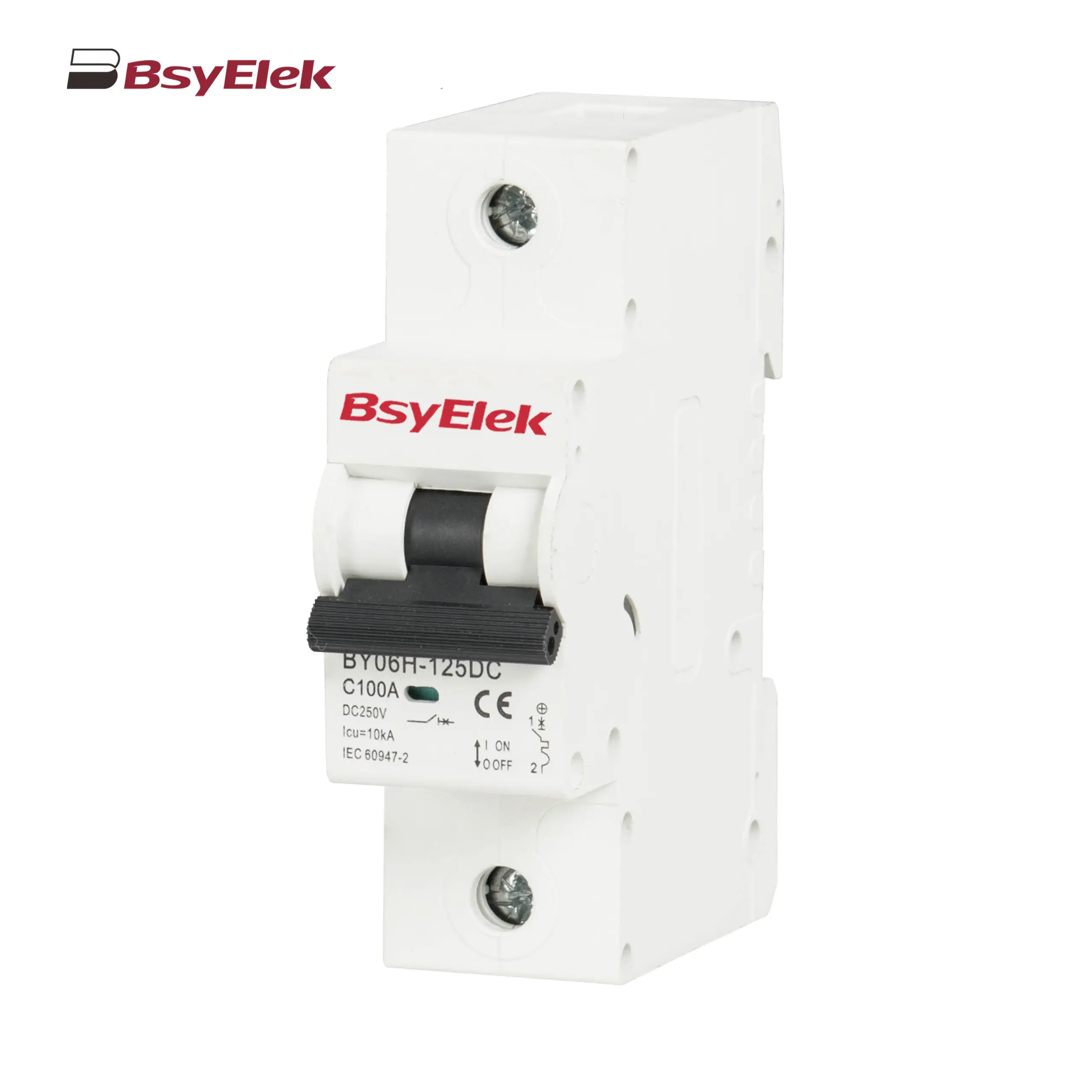
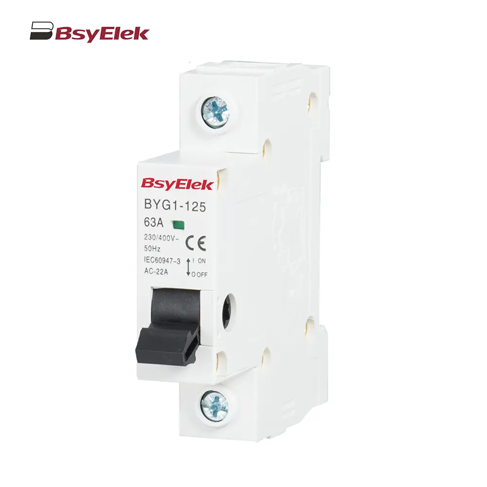
BY06H-125 MCB 10-15KA Miniature Circuit Breaker
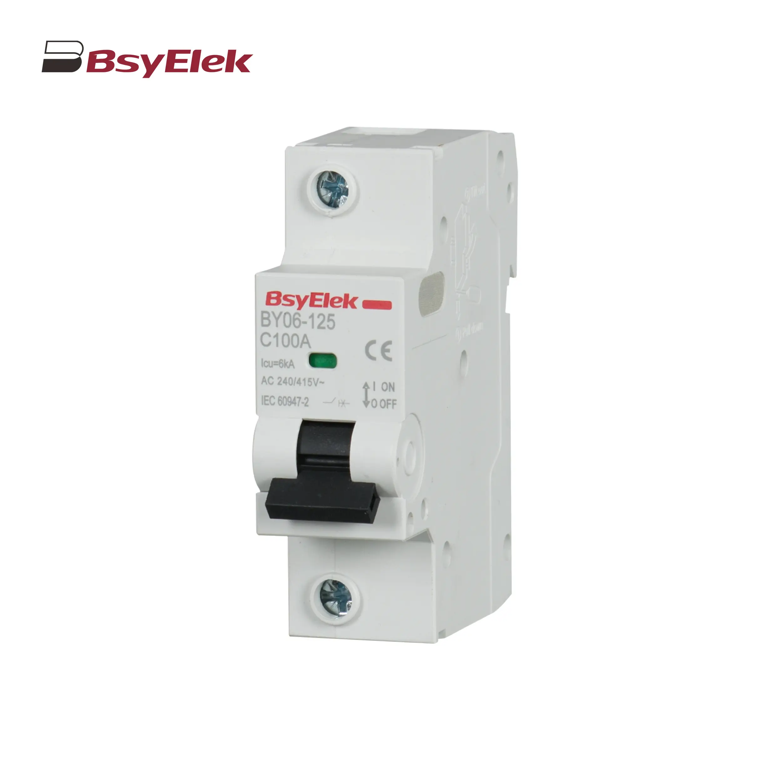
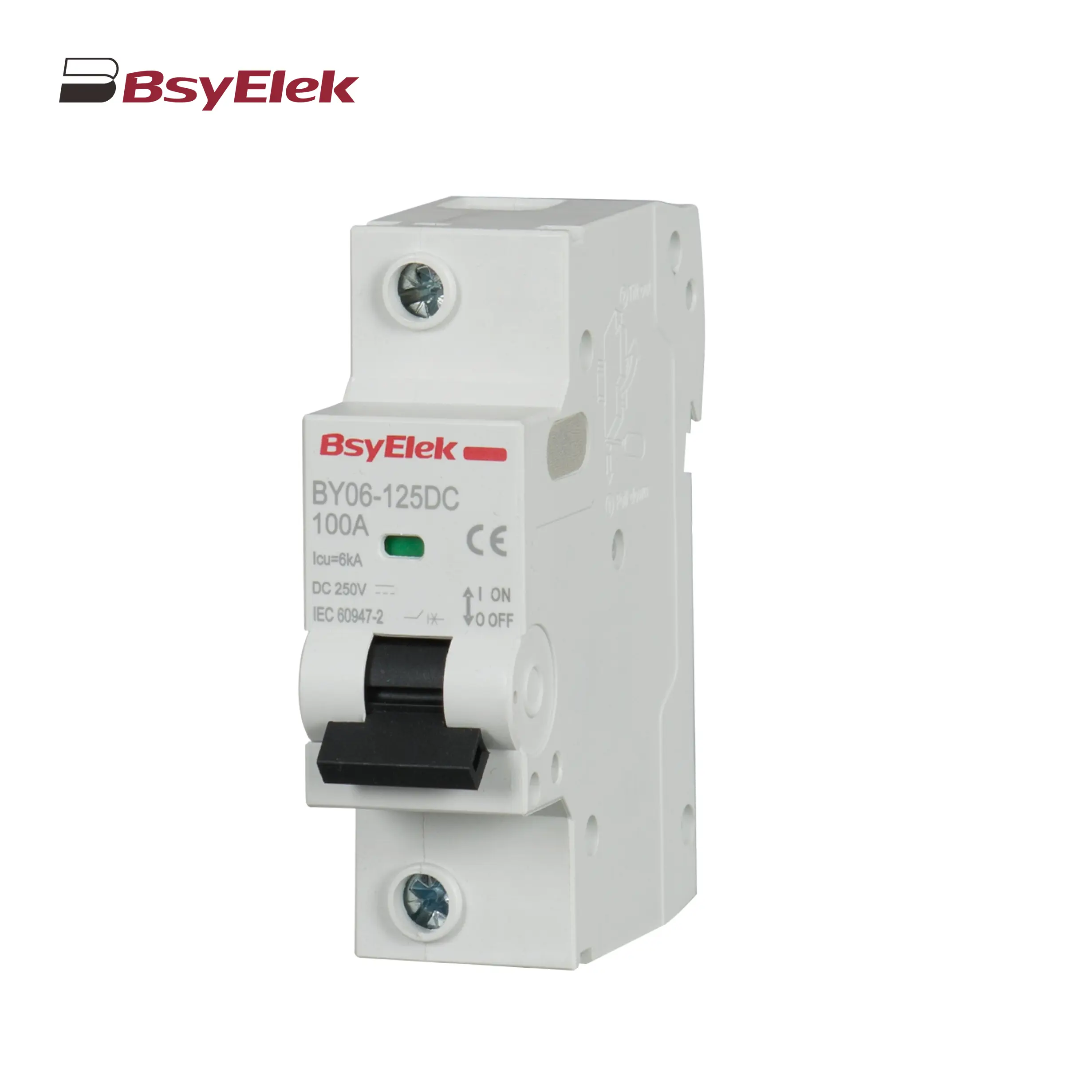
BY06-125 MCB 6KA Miniature Circuit Breaker
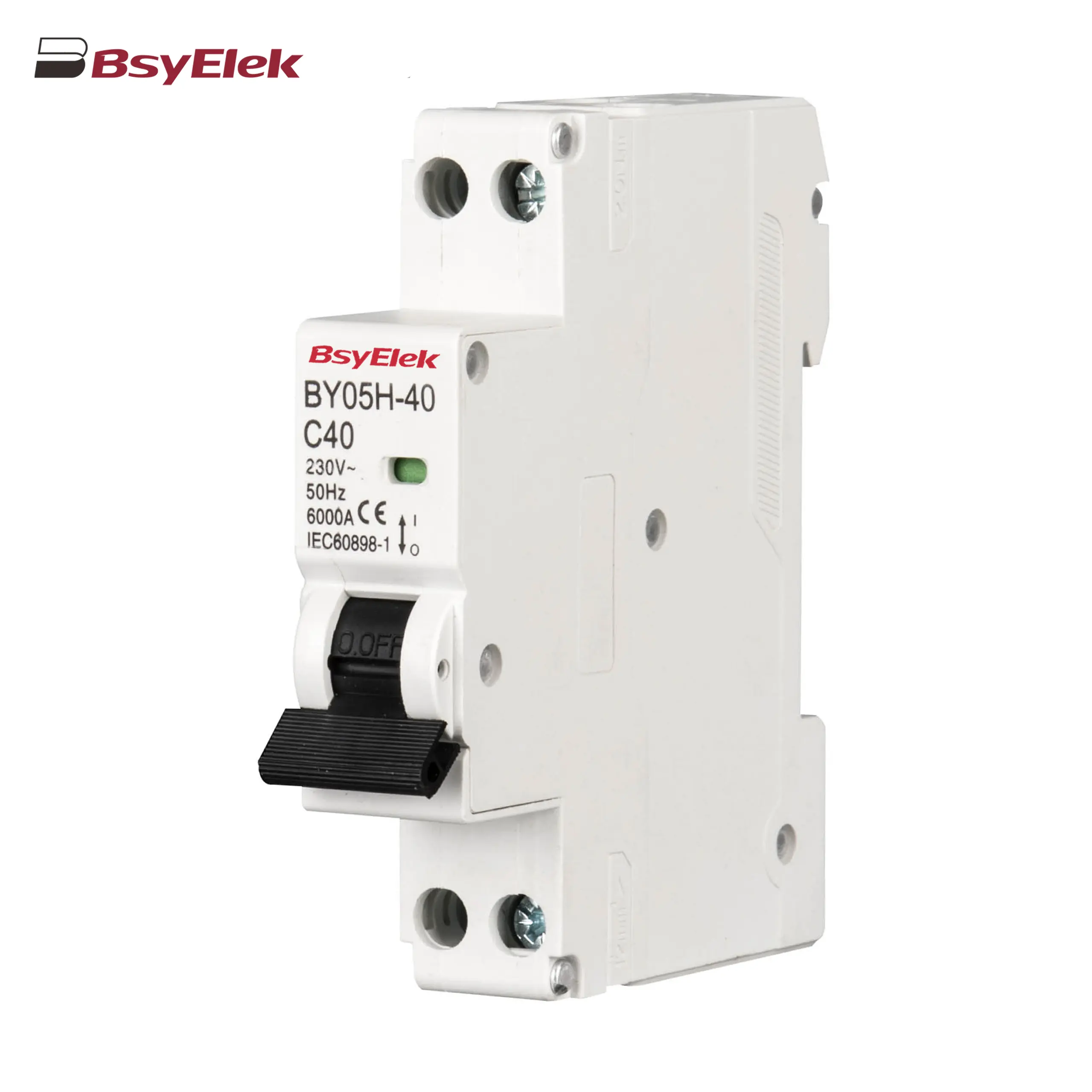
BY05H-40 MCB Single Modular 6KA Miniature Circuit Breaker
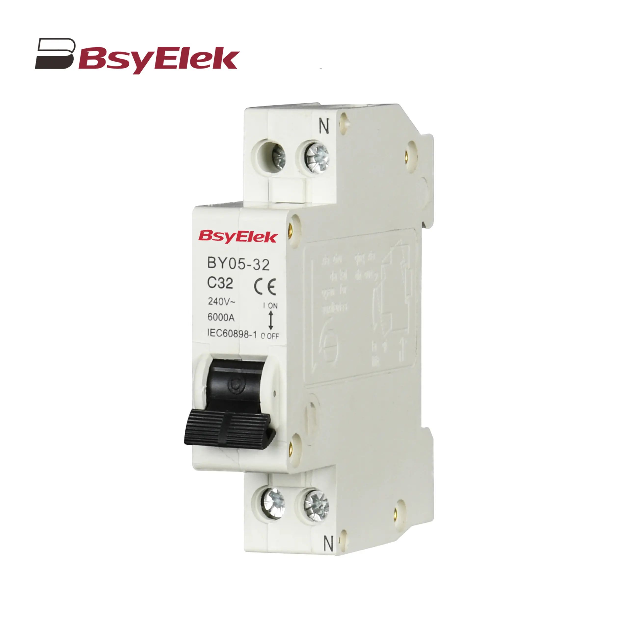
BY05-32 MCB Single Modular 3KA Miniature Circuit Breaker
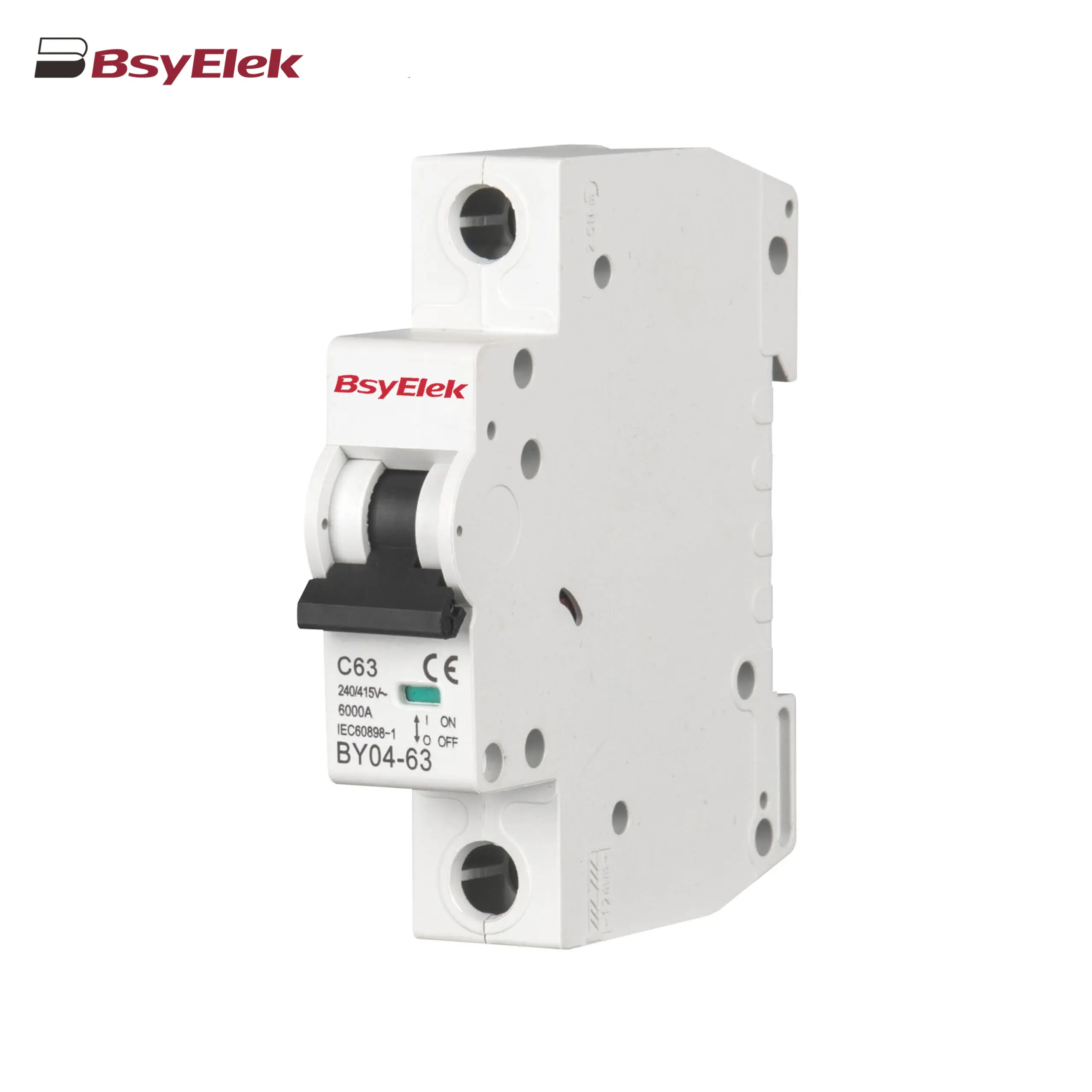
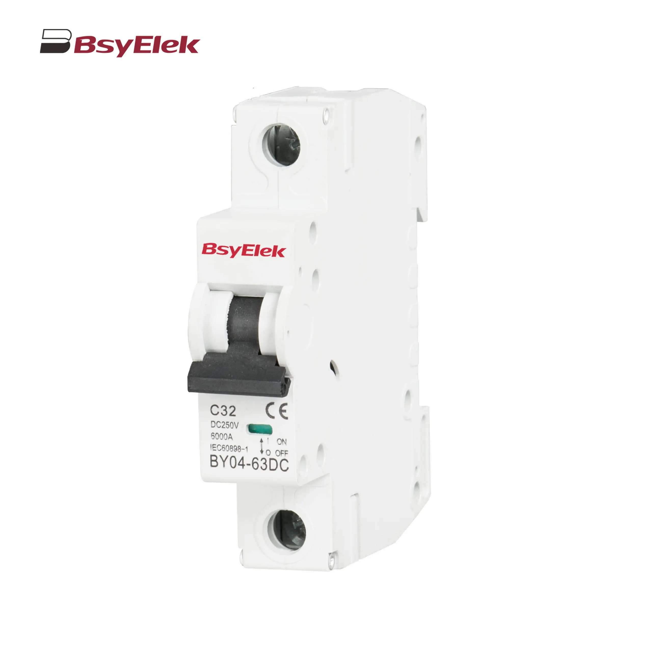
BY04-63 MCB 6-10KA Miniature Circuit Breaker
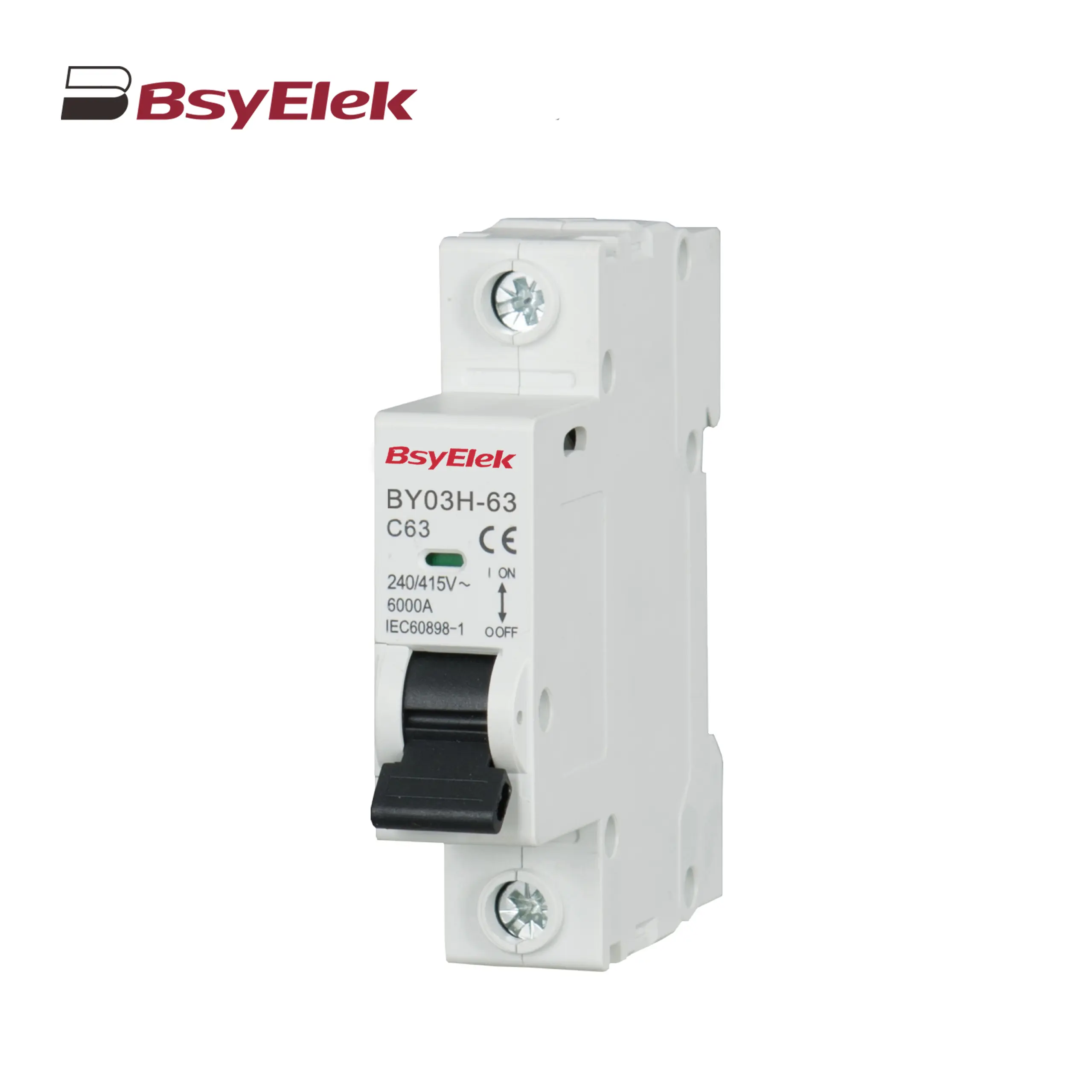
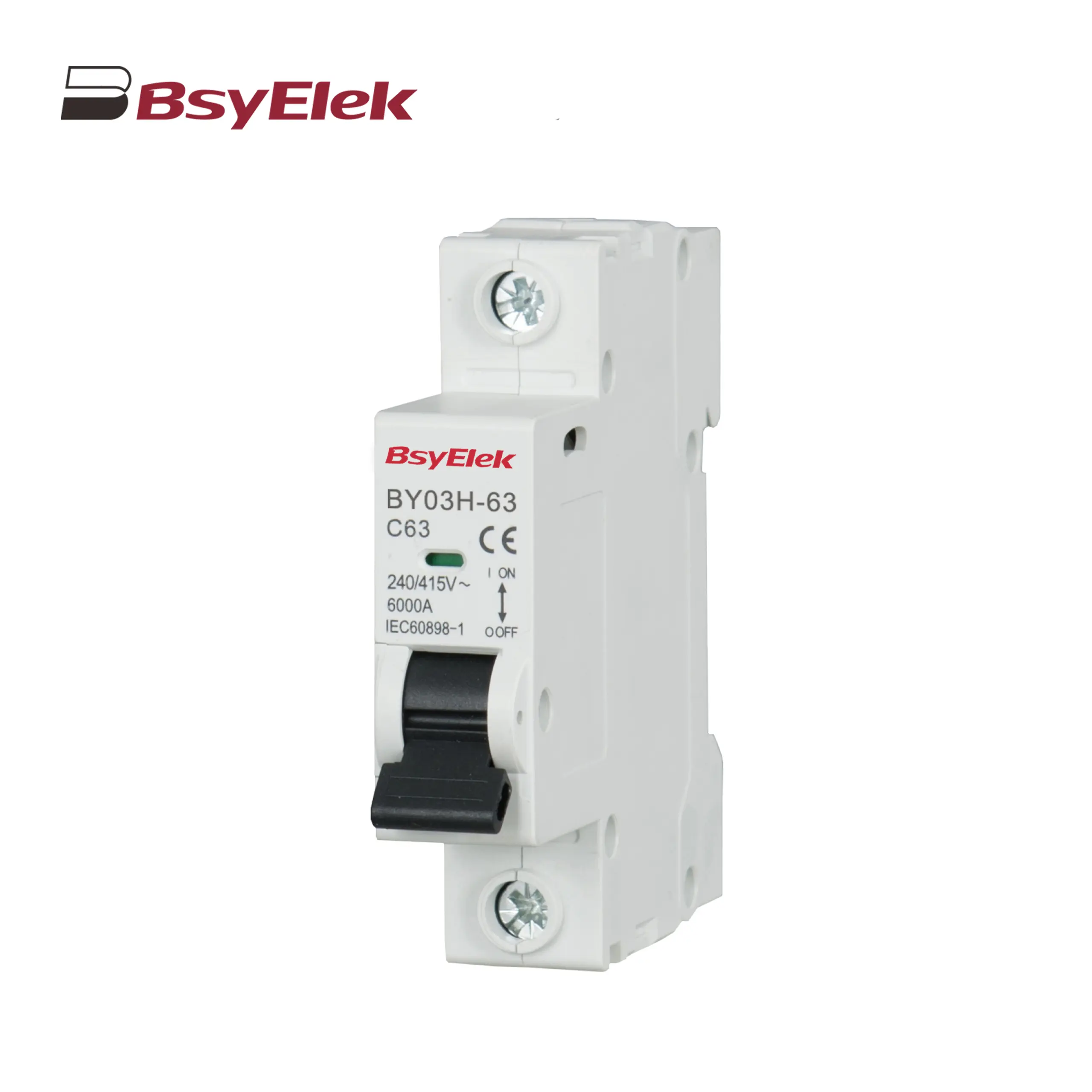
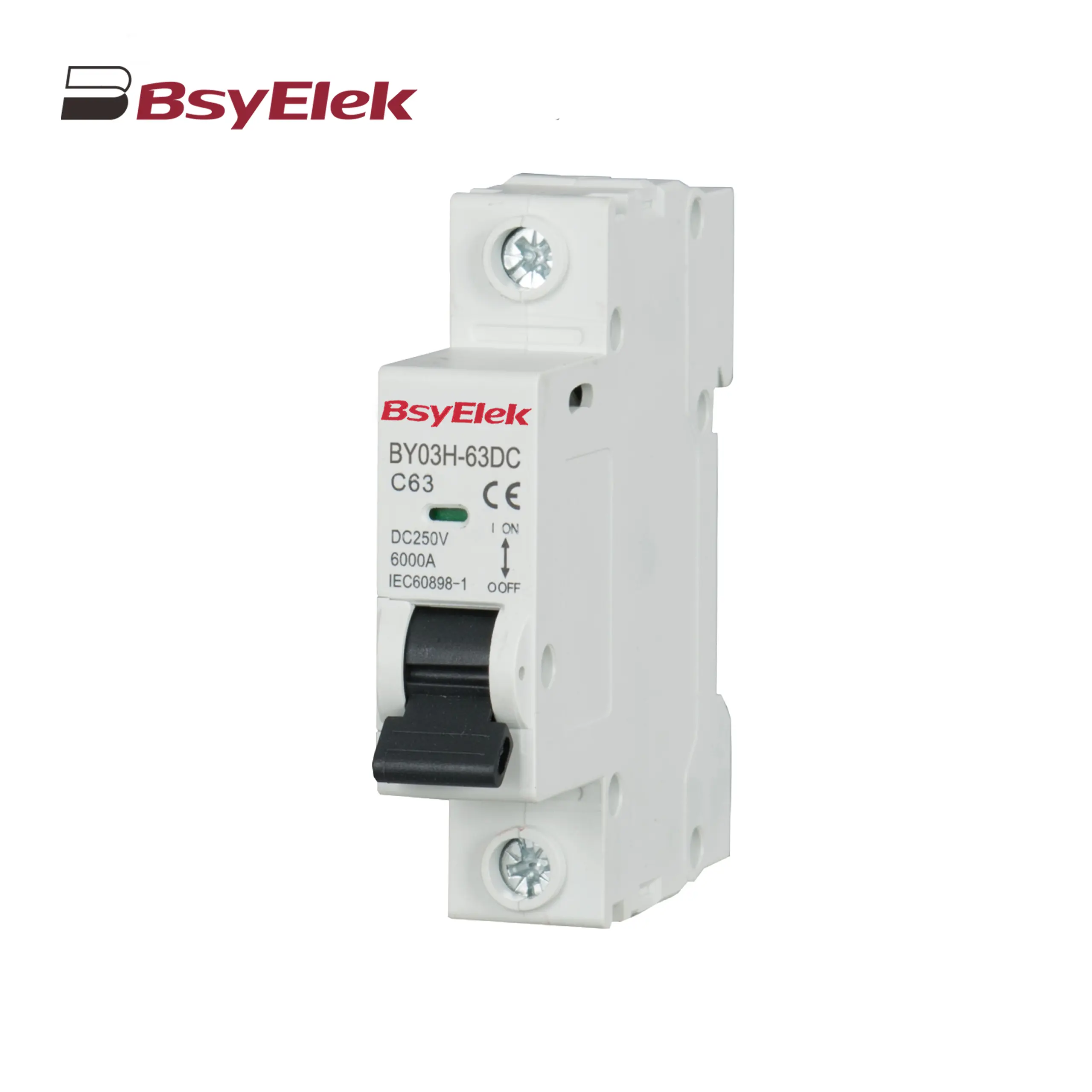
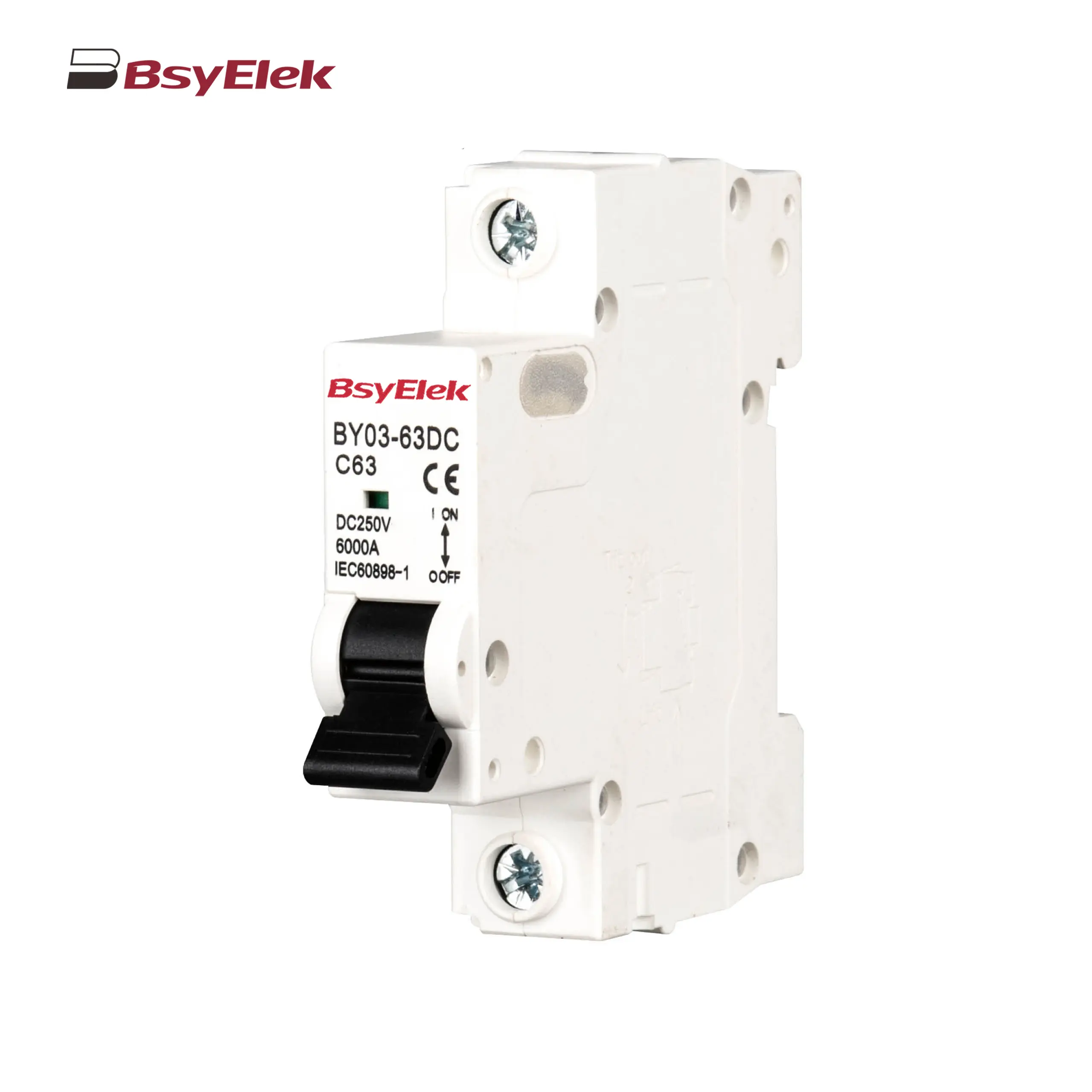
BY03H-63 MCB 6KA Miniature Circuit Breaker
BY03-63 MCB 4.5KA Miniature Circuit Breaker
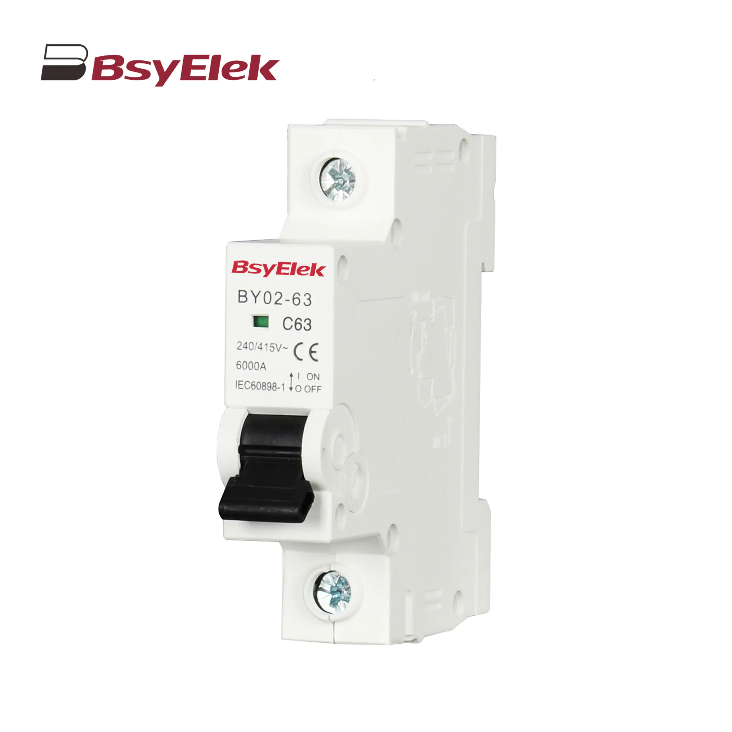
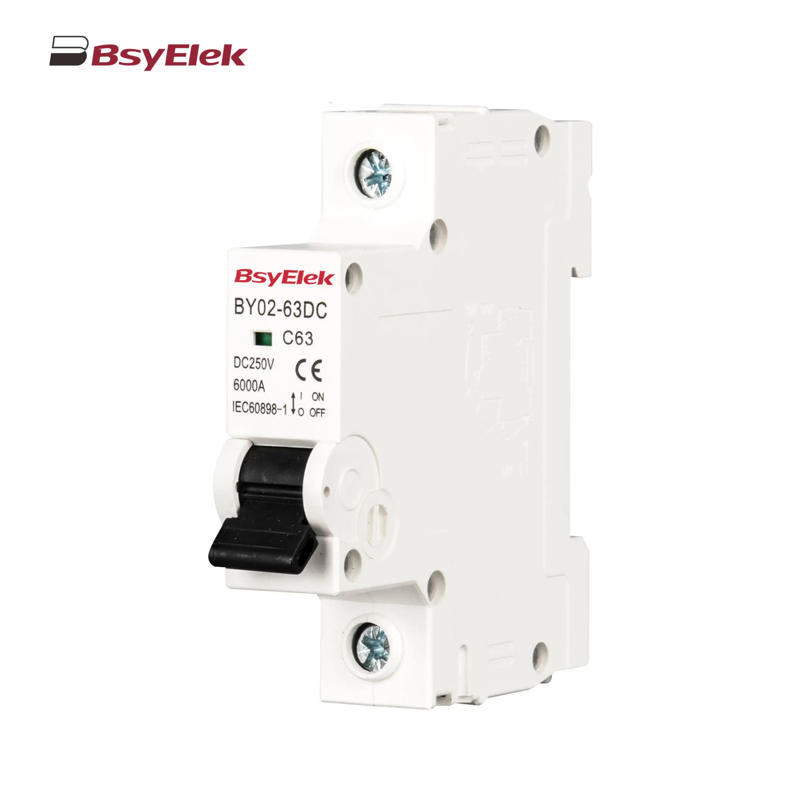
BY02-63 MCB 3kA Miniature Circuit Breaker
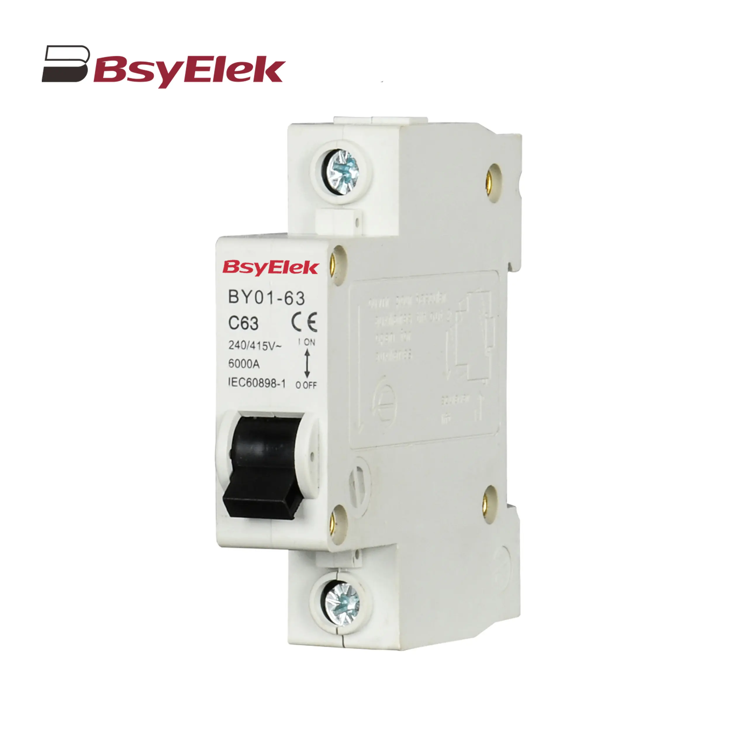
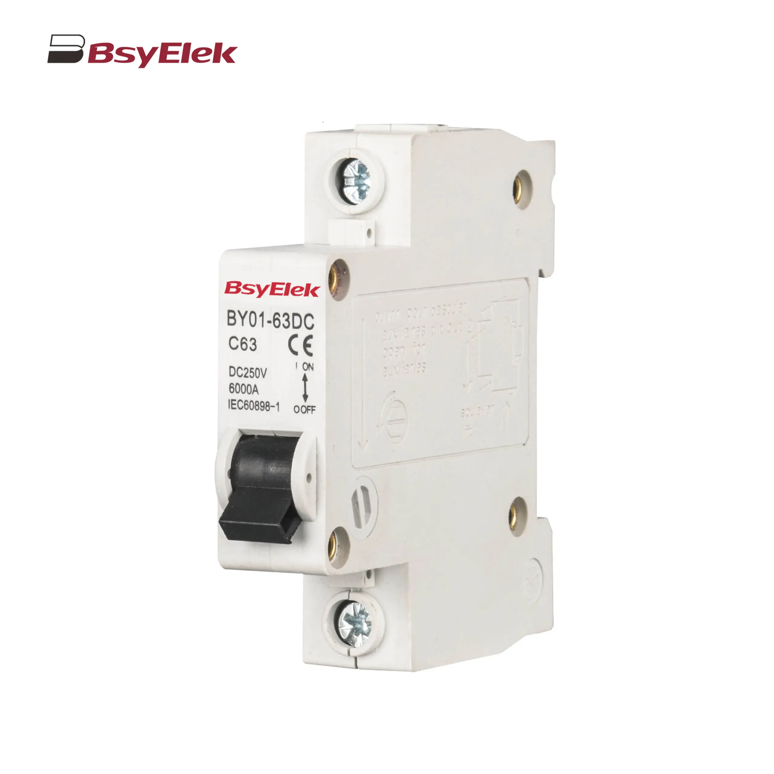
BY01-63 MCB 3kA Miniature Circuit Breaker
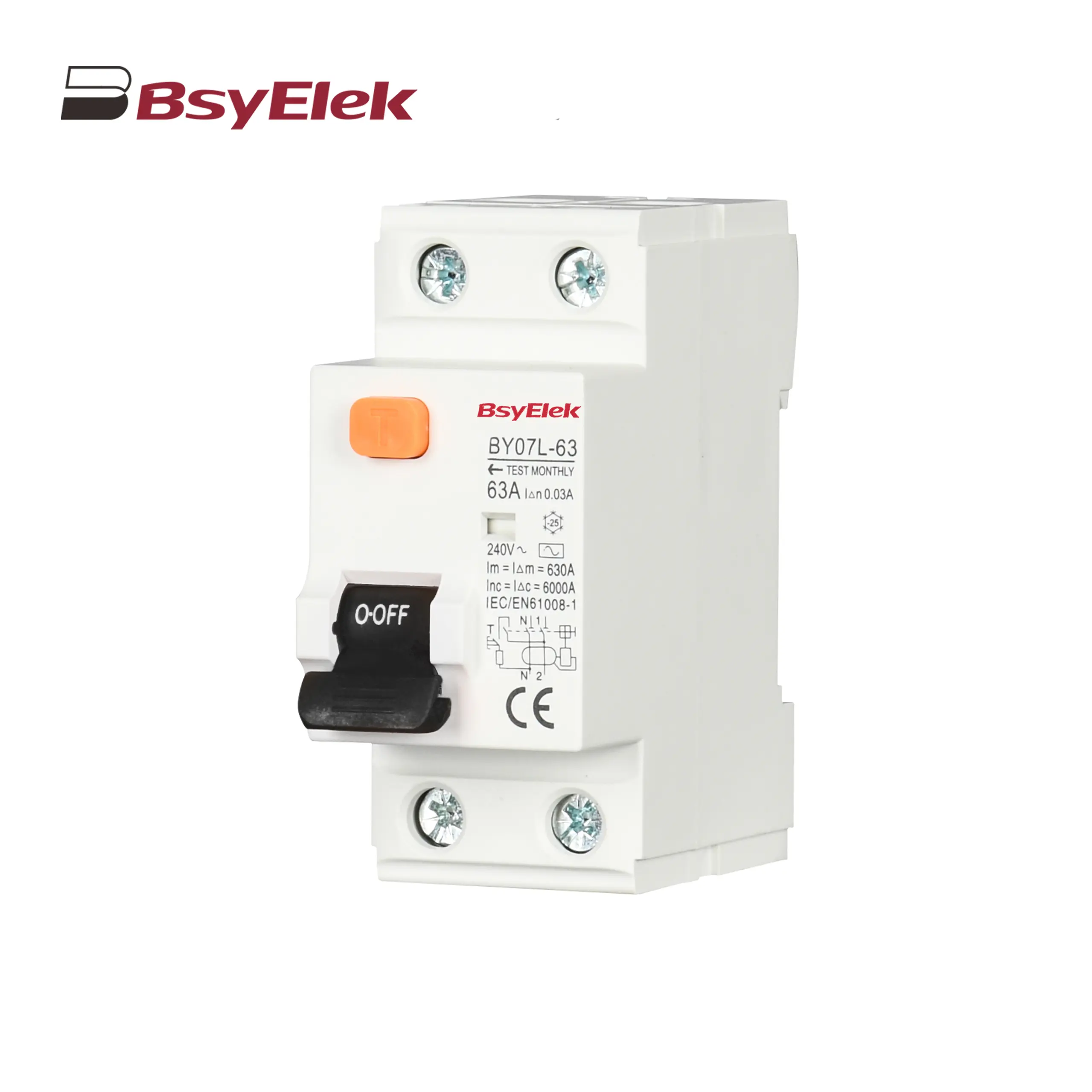
BY07L-63 RCCB 6KA Residual Current Circuit Breaker
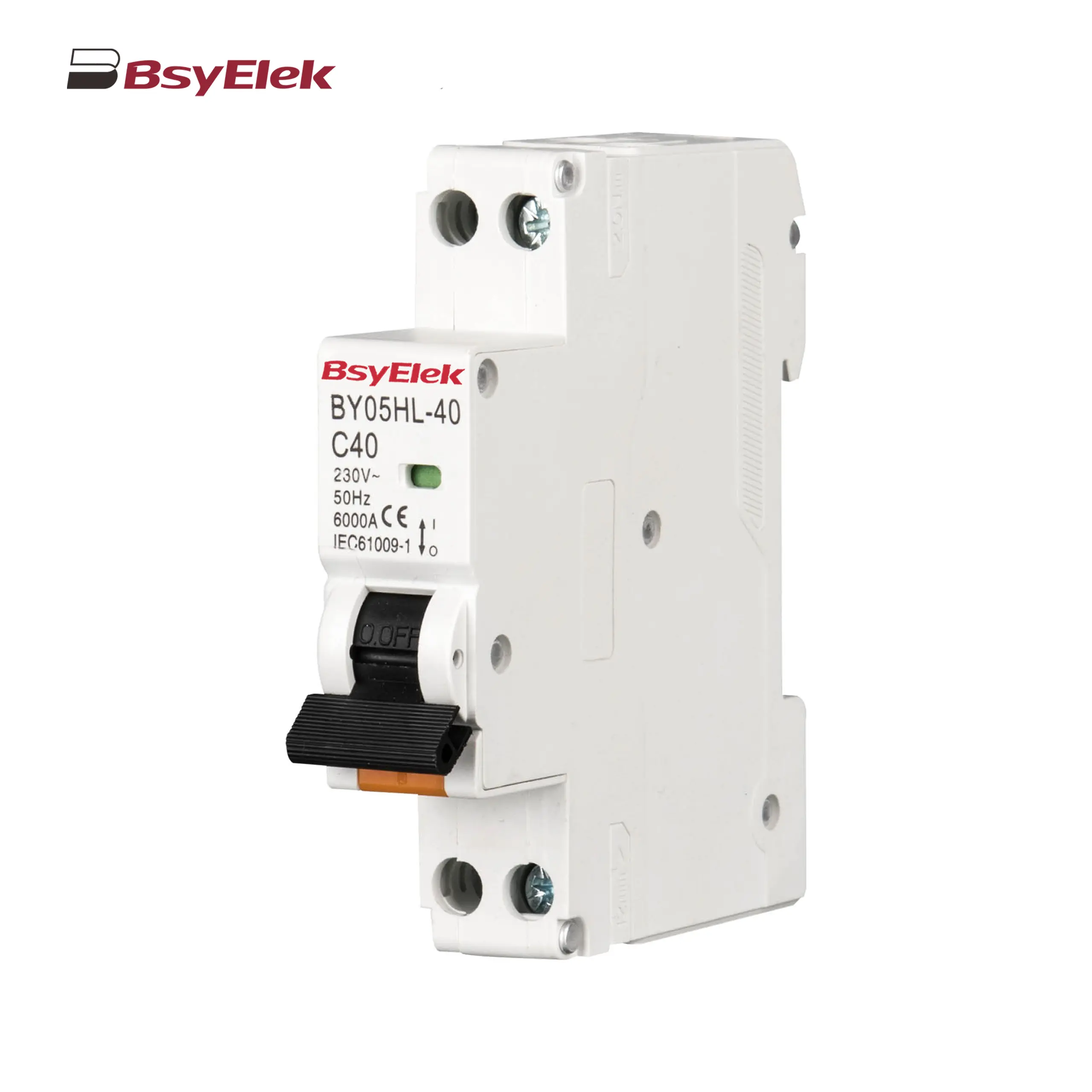
BY05HL-40 RCBO 6KA Residual Current Circuit Breaker with Over-current Protection
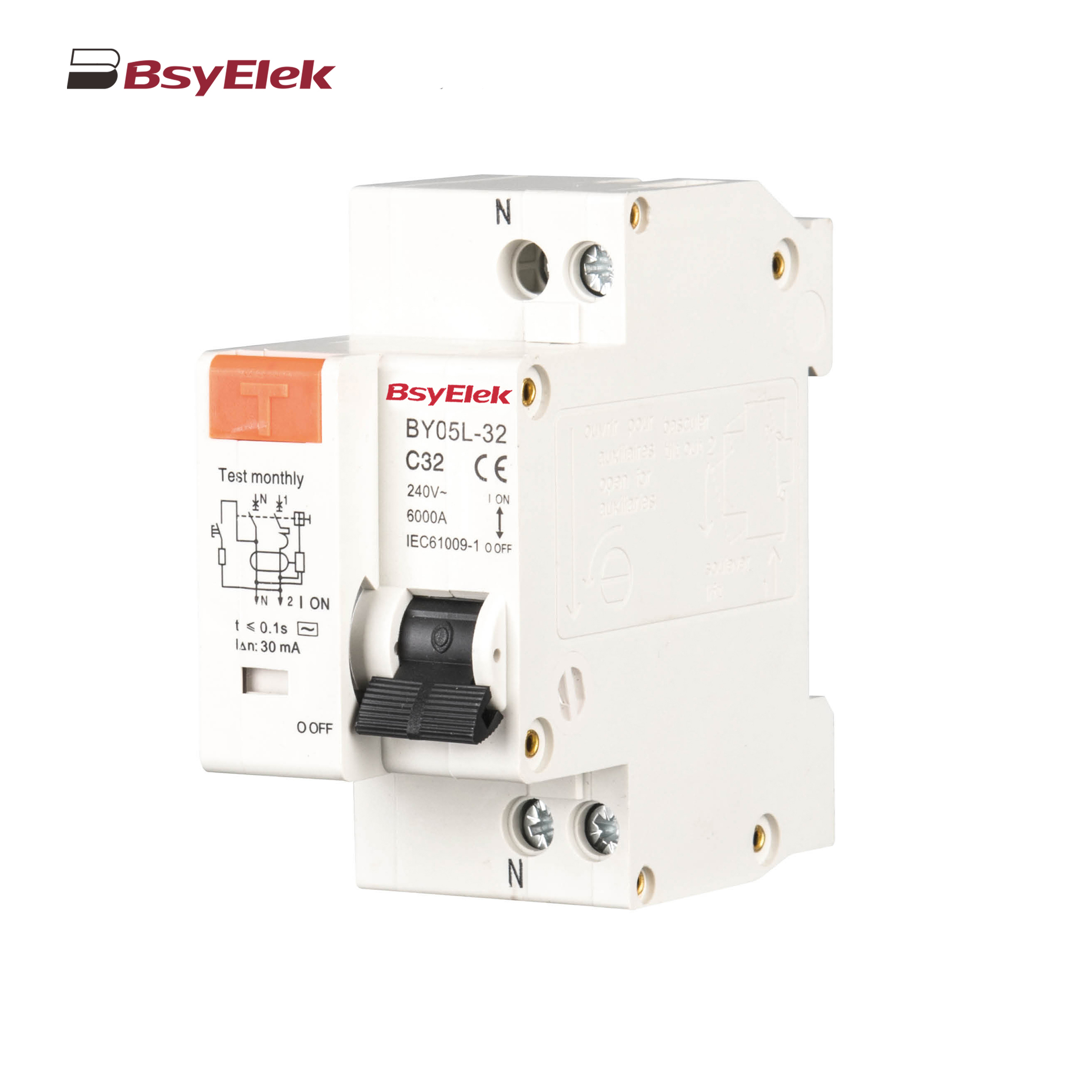
BY05L-32 RCBO 3KA Residual Current Circuit Breaker with Over-current Protection
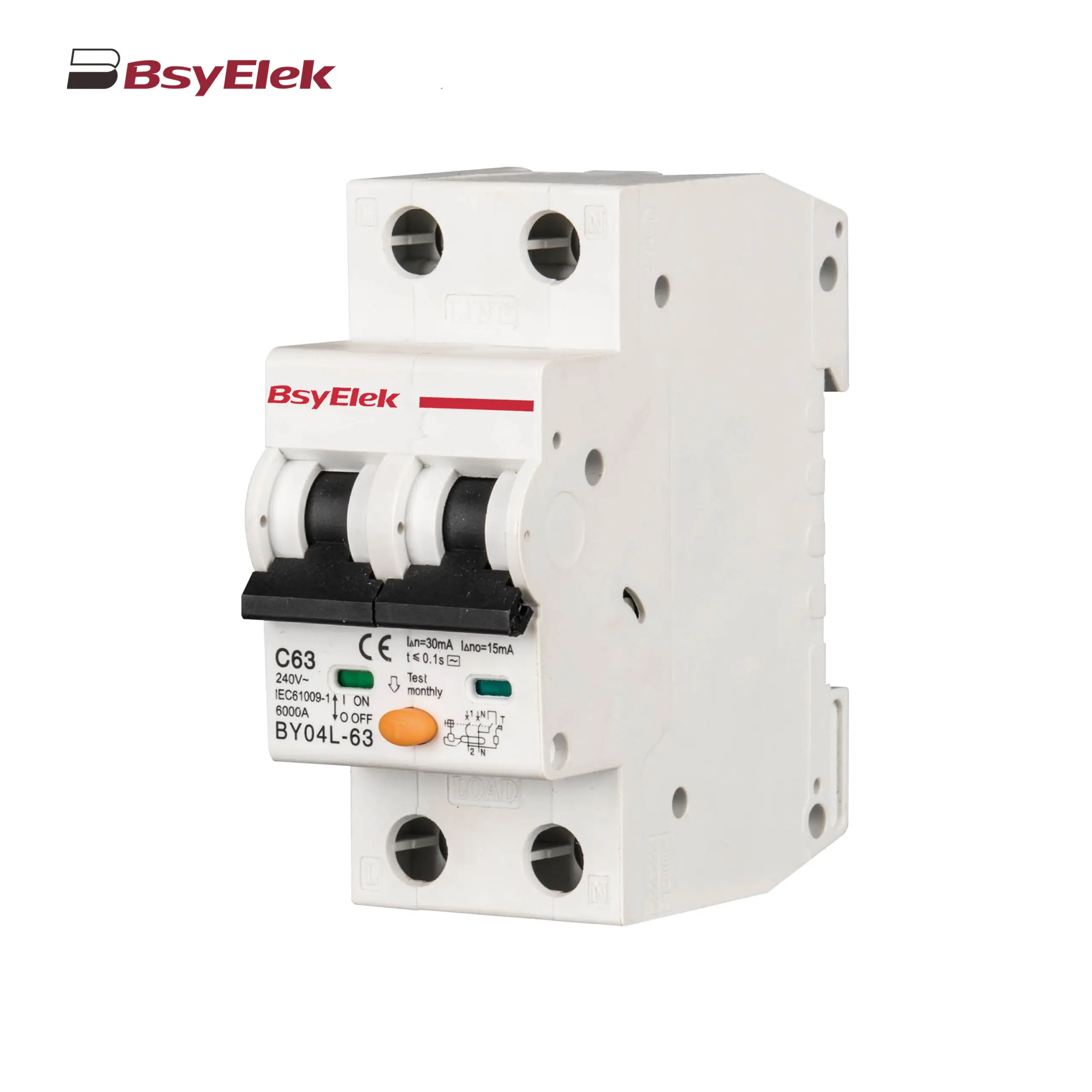
BY04L-63 RCBO 6KA Residual Current Circuit Breaker with Over-current Protection
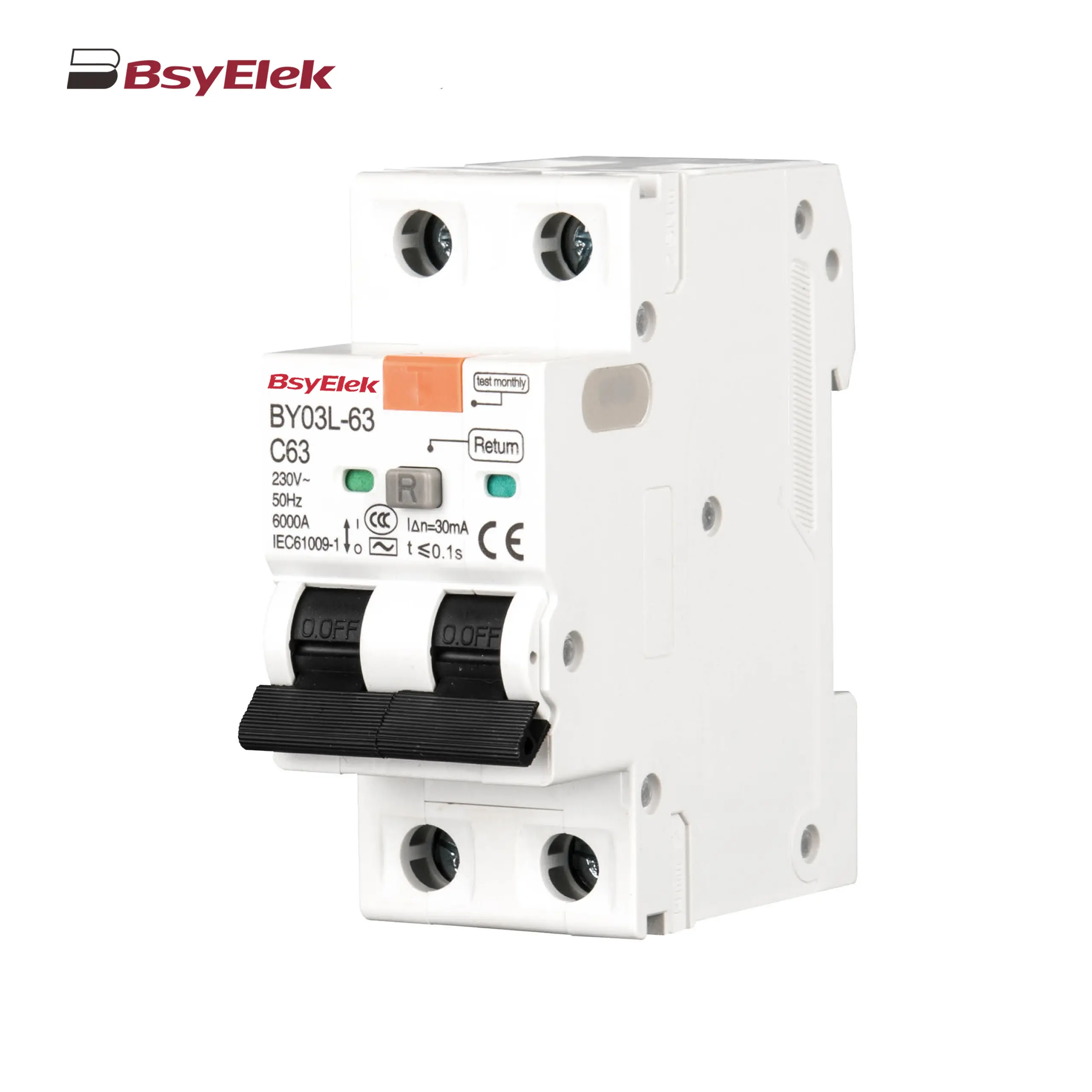
BY03L-63 RCBO 4.5KA Residual Current Circuit Breaker with Over-current Protection
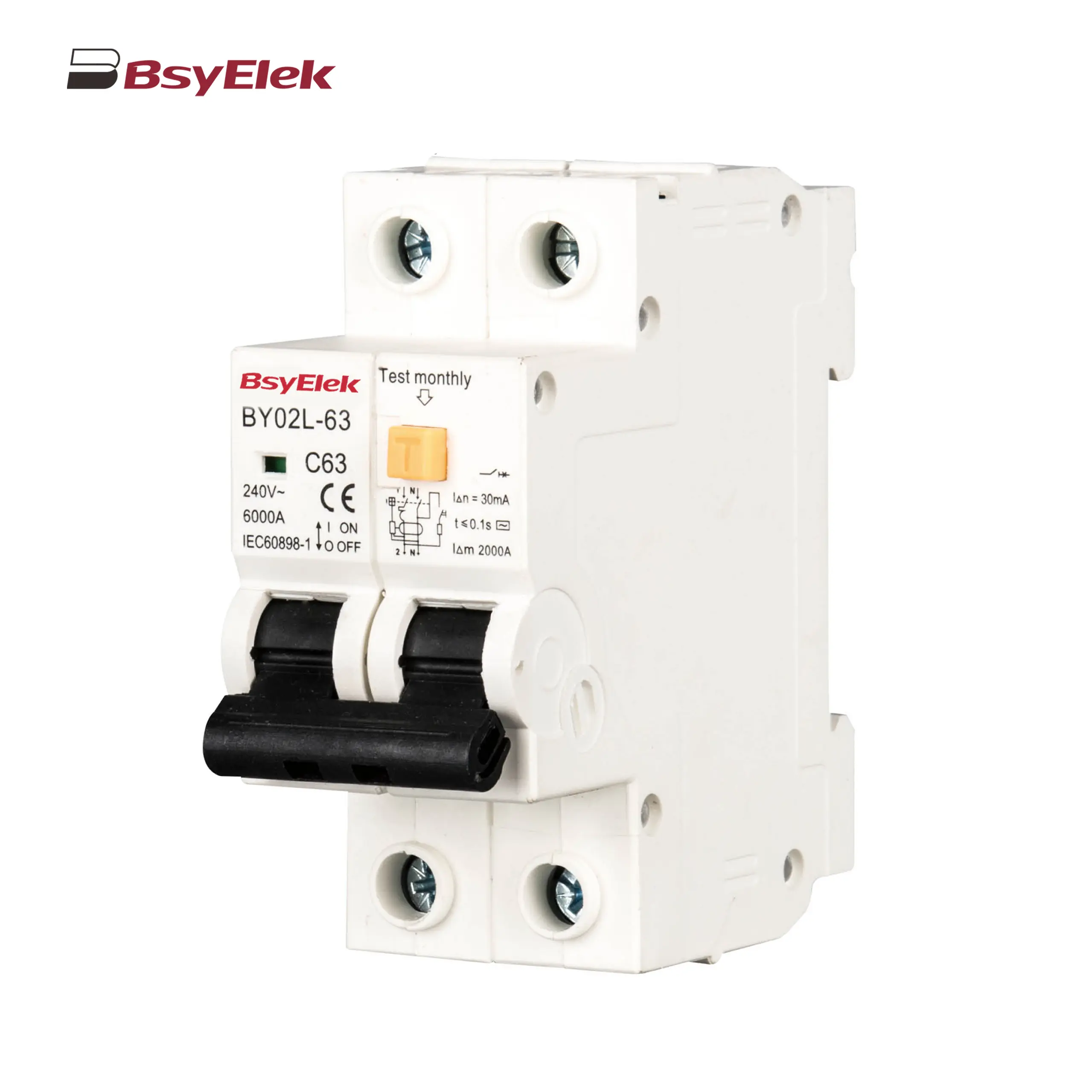
BY02L-63 RCBO 3KA Residual Current Circuit Breaker with Over-current Protection
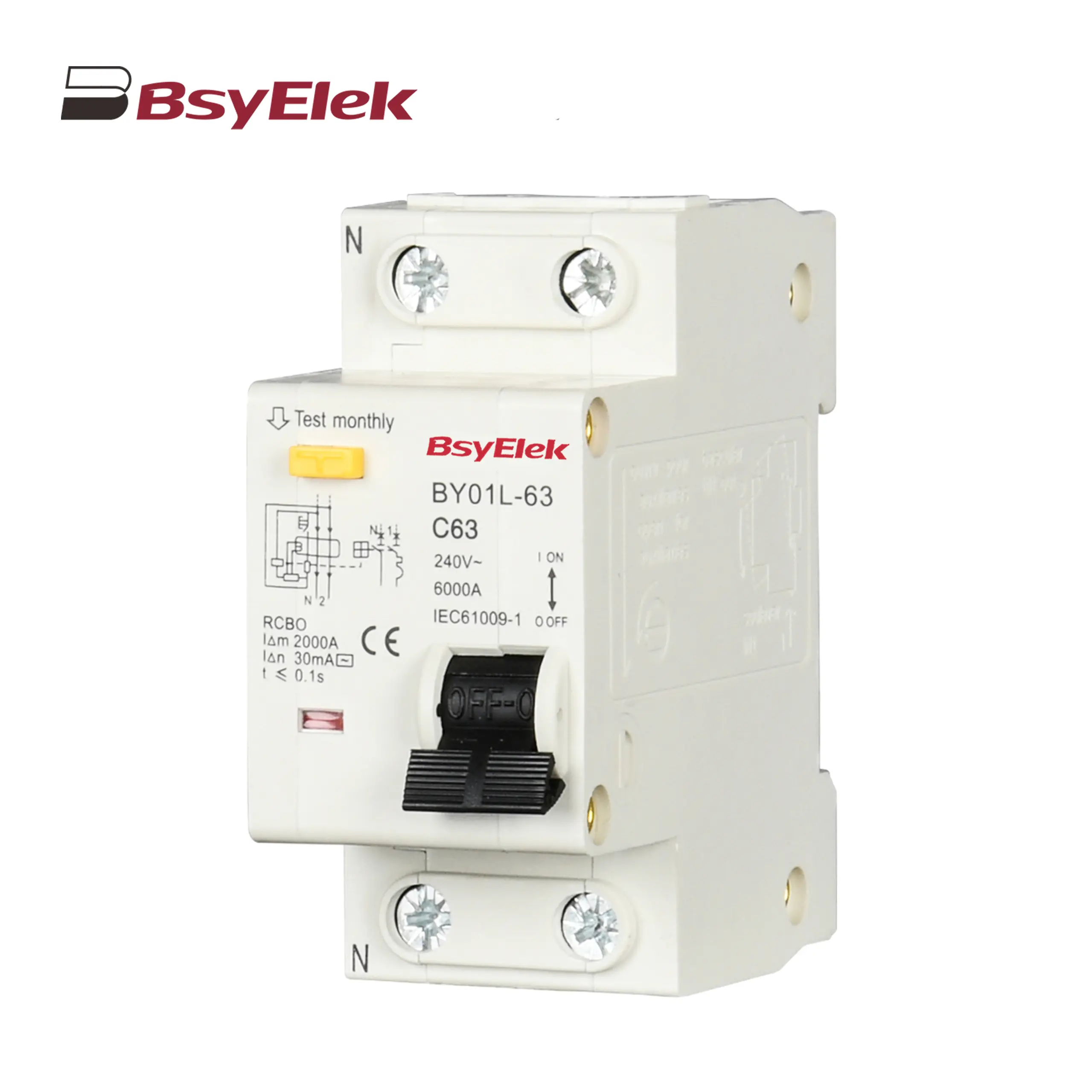
BY01L-63 RCBO 1P+N 3KA Residual Current Circuit Breaker with Over-current Protection
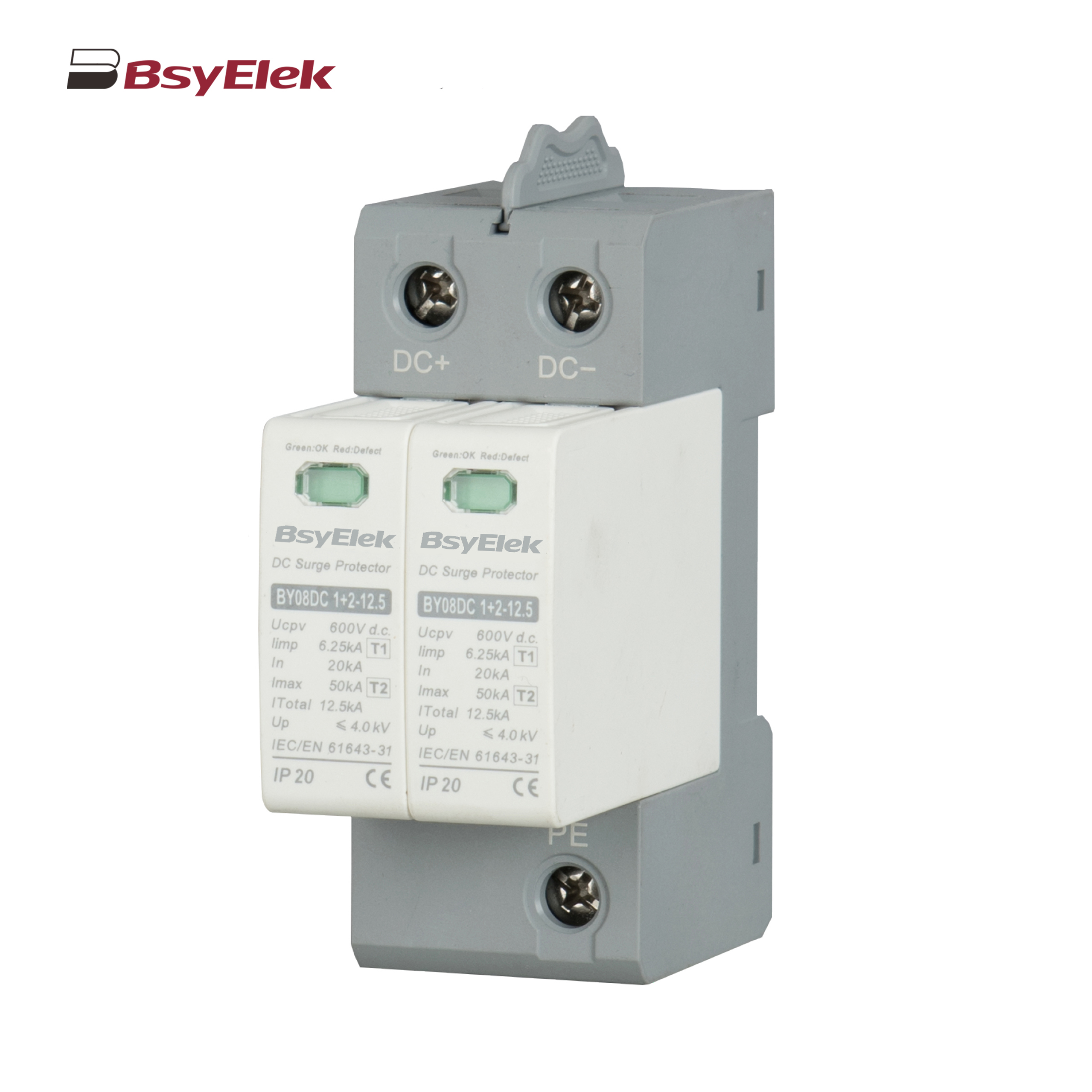
BY06H-125DC MCB 10-15kA DC Miniature Circuit Breaker
BY06-125DC MCB 6kA DC Miniature Circuit Breaker
BY04-63DC MCB 6-10kA DC Miniature Circuit Breaker
BY03H-63DC MCB 6kA DC Miniature Circuit Breaker
BY03-63DC MCB 4.5kA DC Miniature Circuit Breaker
BY02-63DC MCB 3kA DC Miniature Circuit Breaker
BY01-63DC MCB 3kA DC Miniature Circuit Breaker
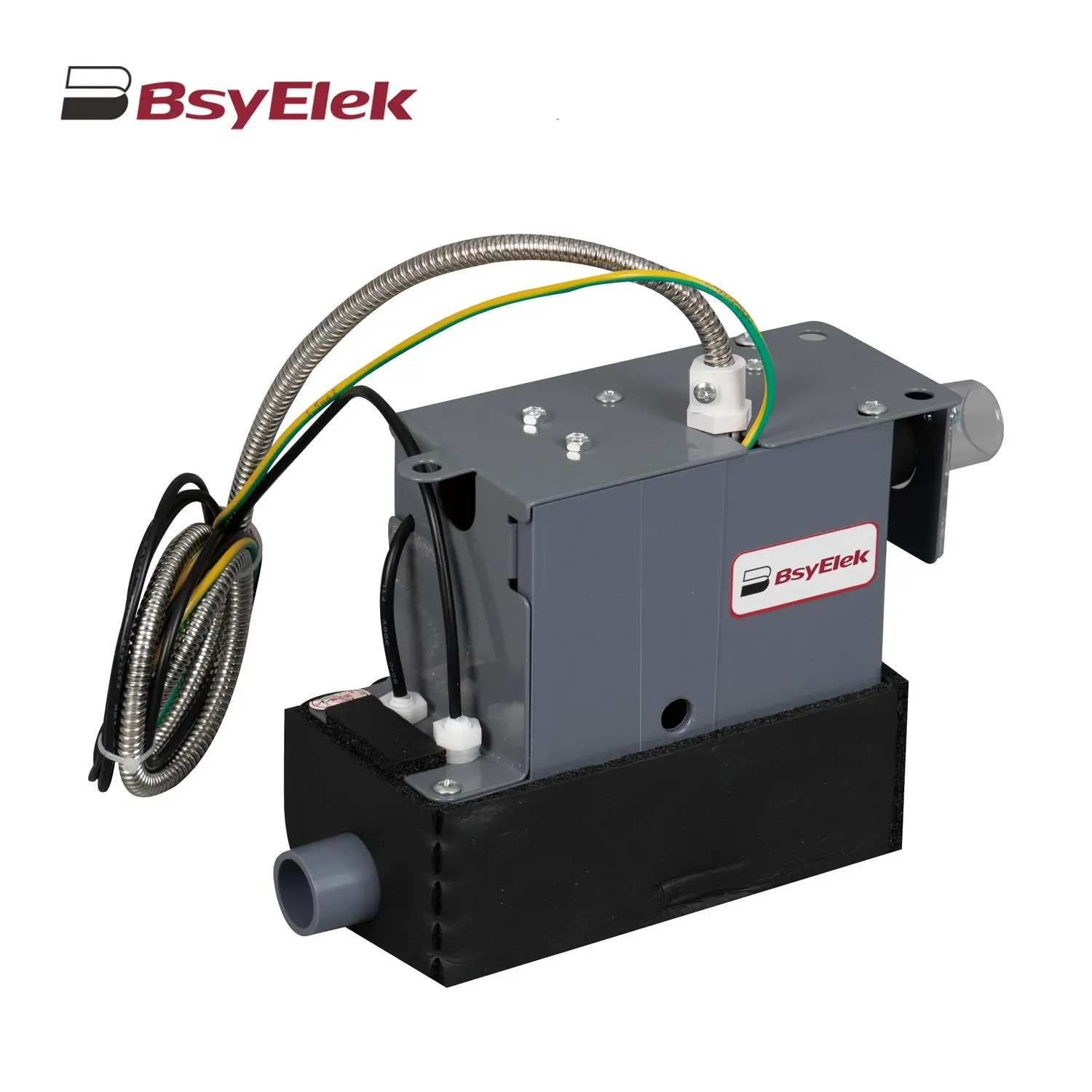
BY-5018 1.8M Engineering Drainage Pump
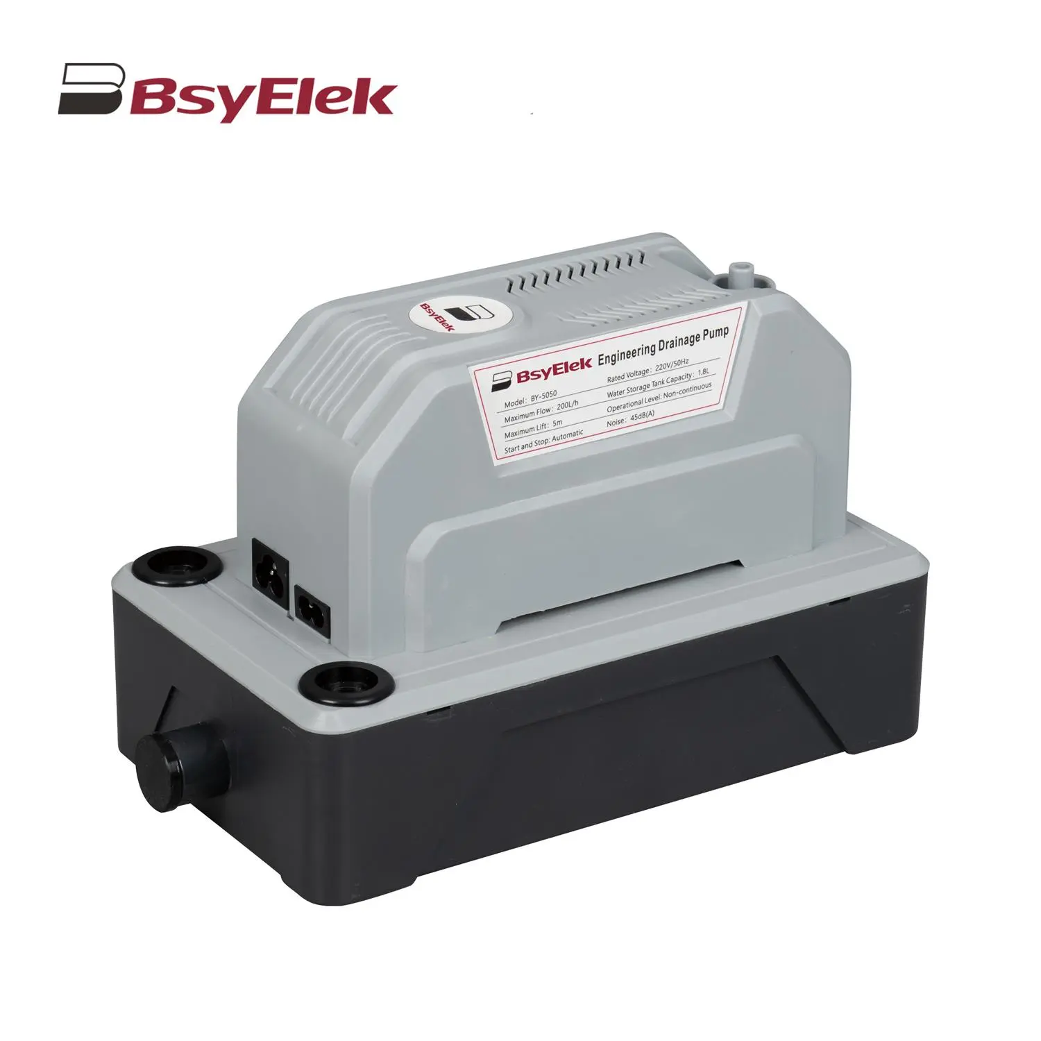
BY-5050 5M Engineering Drainage Pump
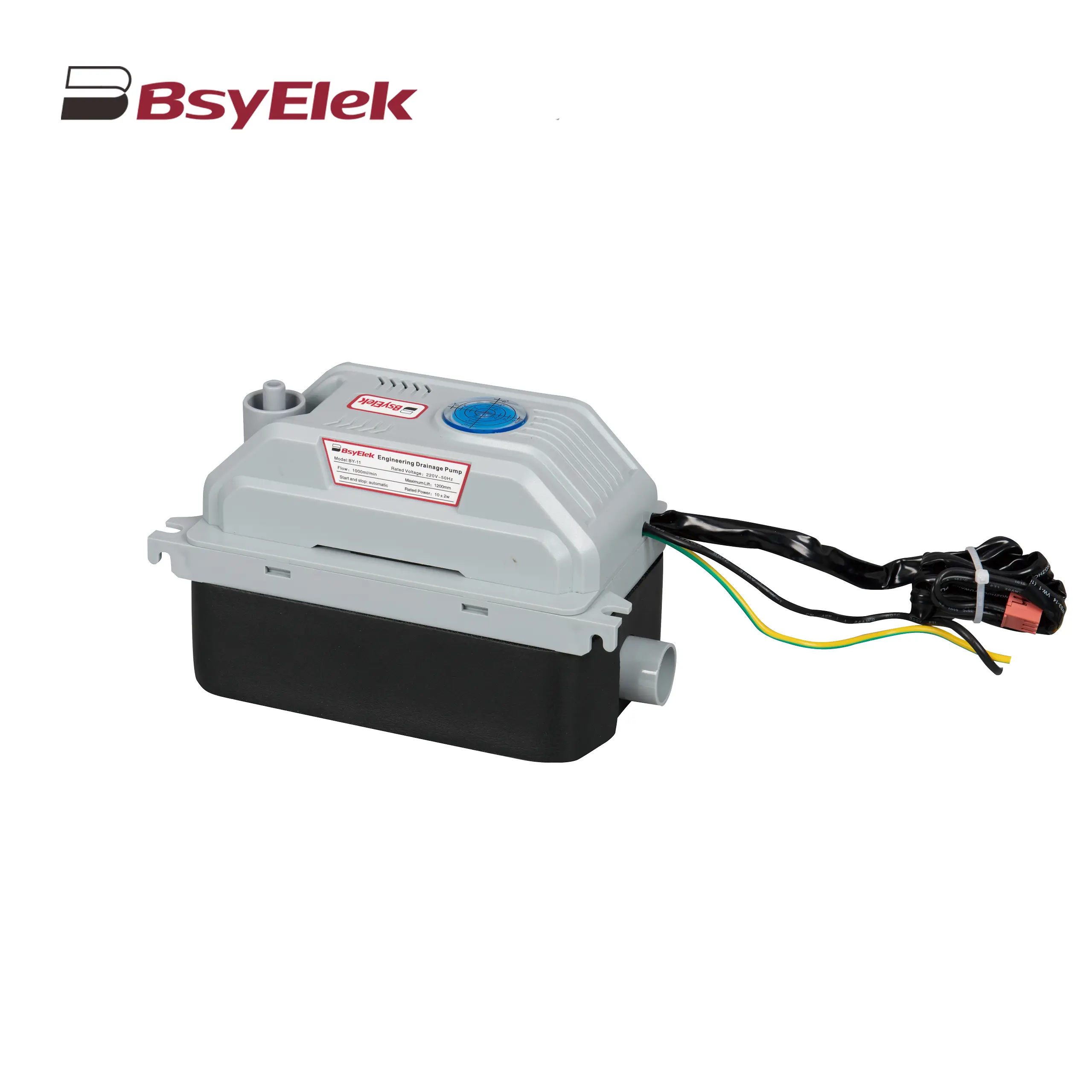
BY-11 1.2M Engineering Drainage Pump
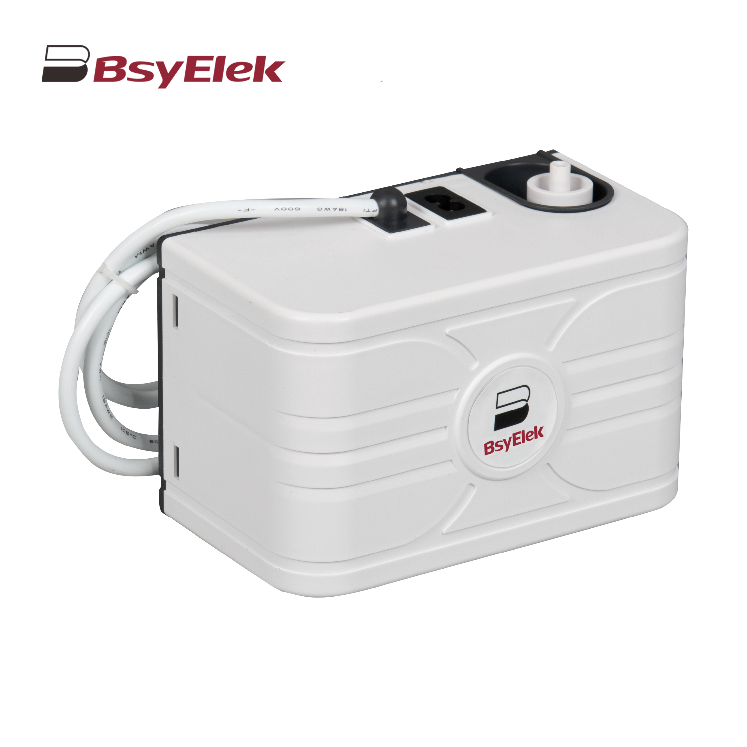
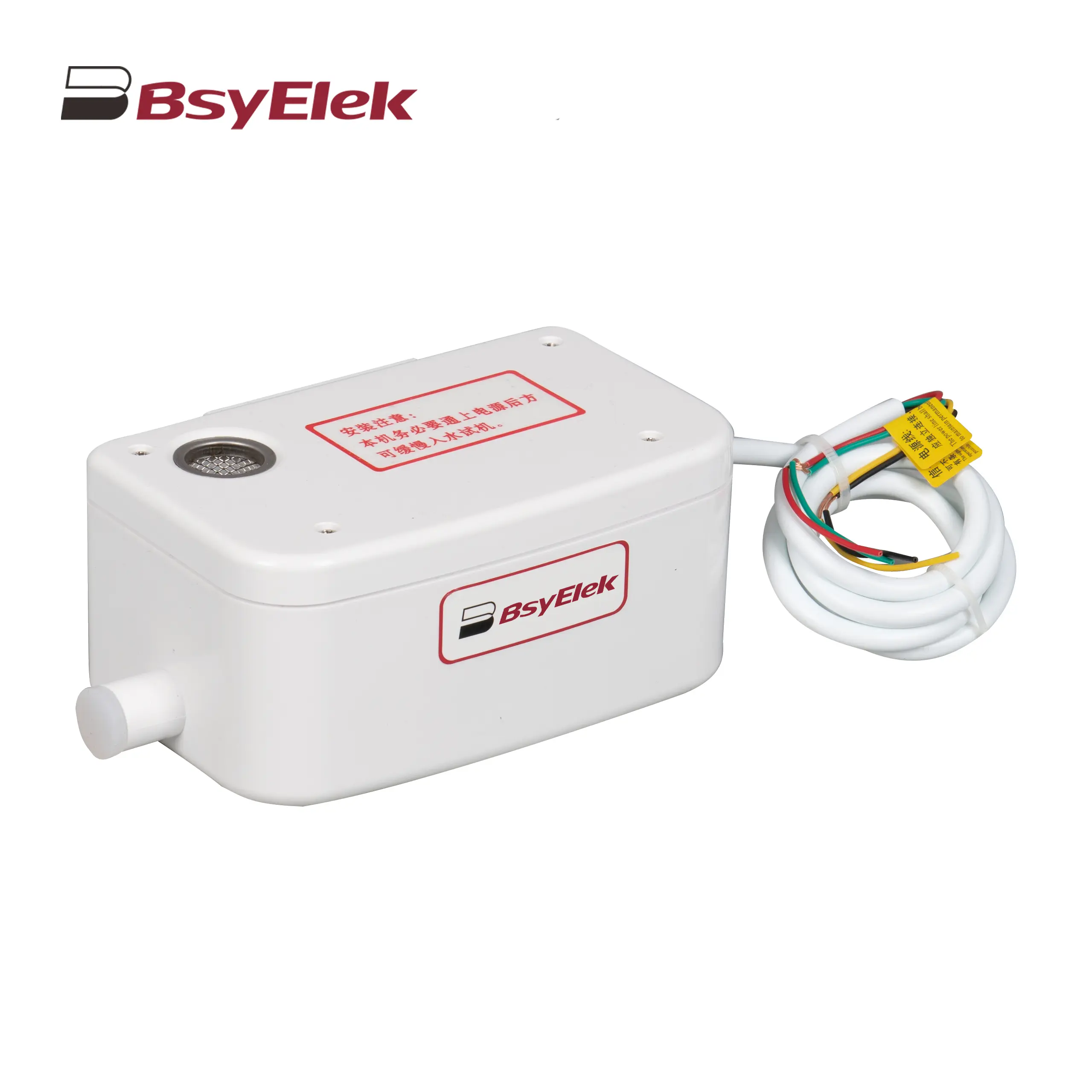
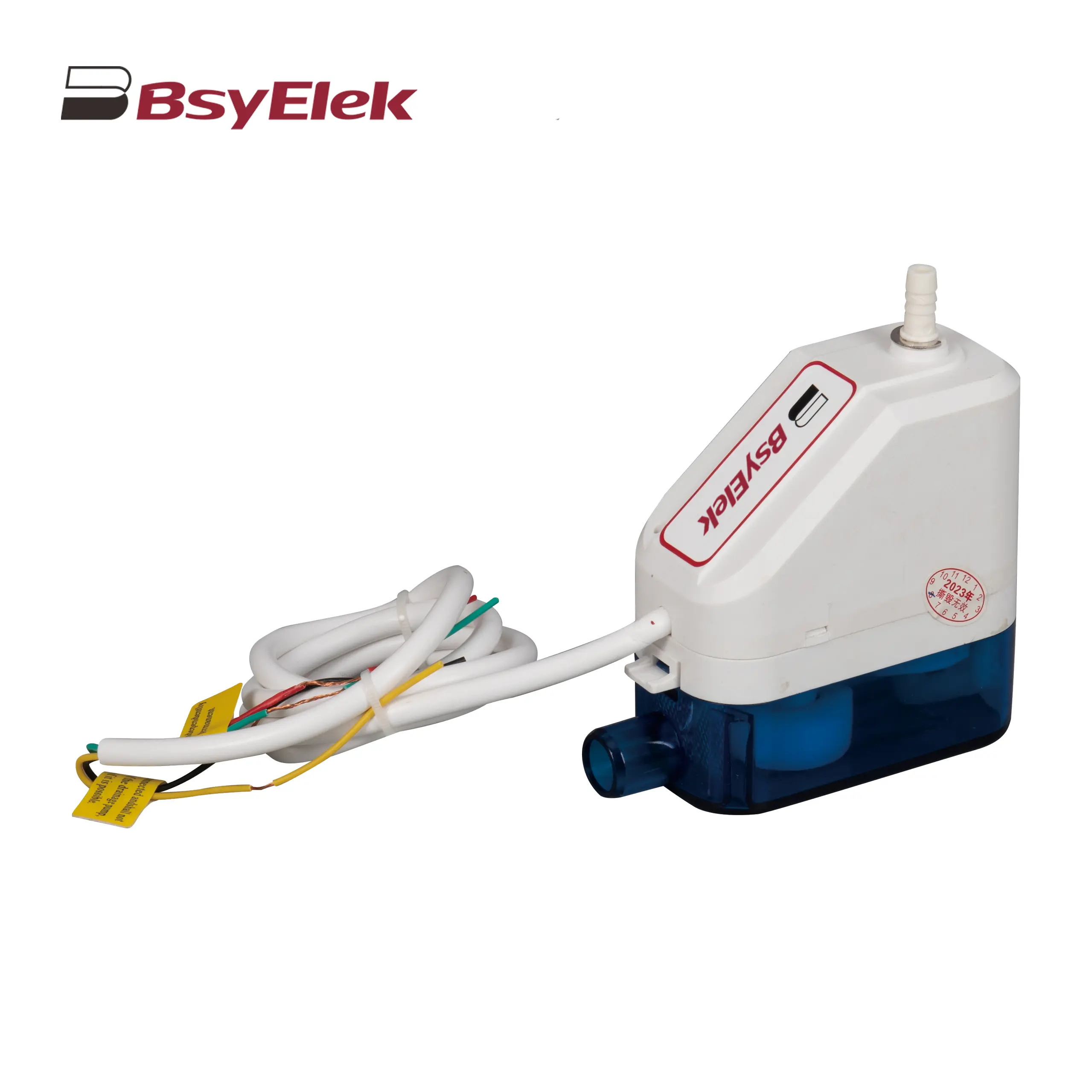
SBH-05 0.7M Original Drainage Pump of Duct Type Air Conditioner
BY-24A/40A 10M Drainage Pump of Air Conditioner
BY-50A 12M Drainage Pump of Air Conditioner
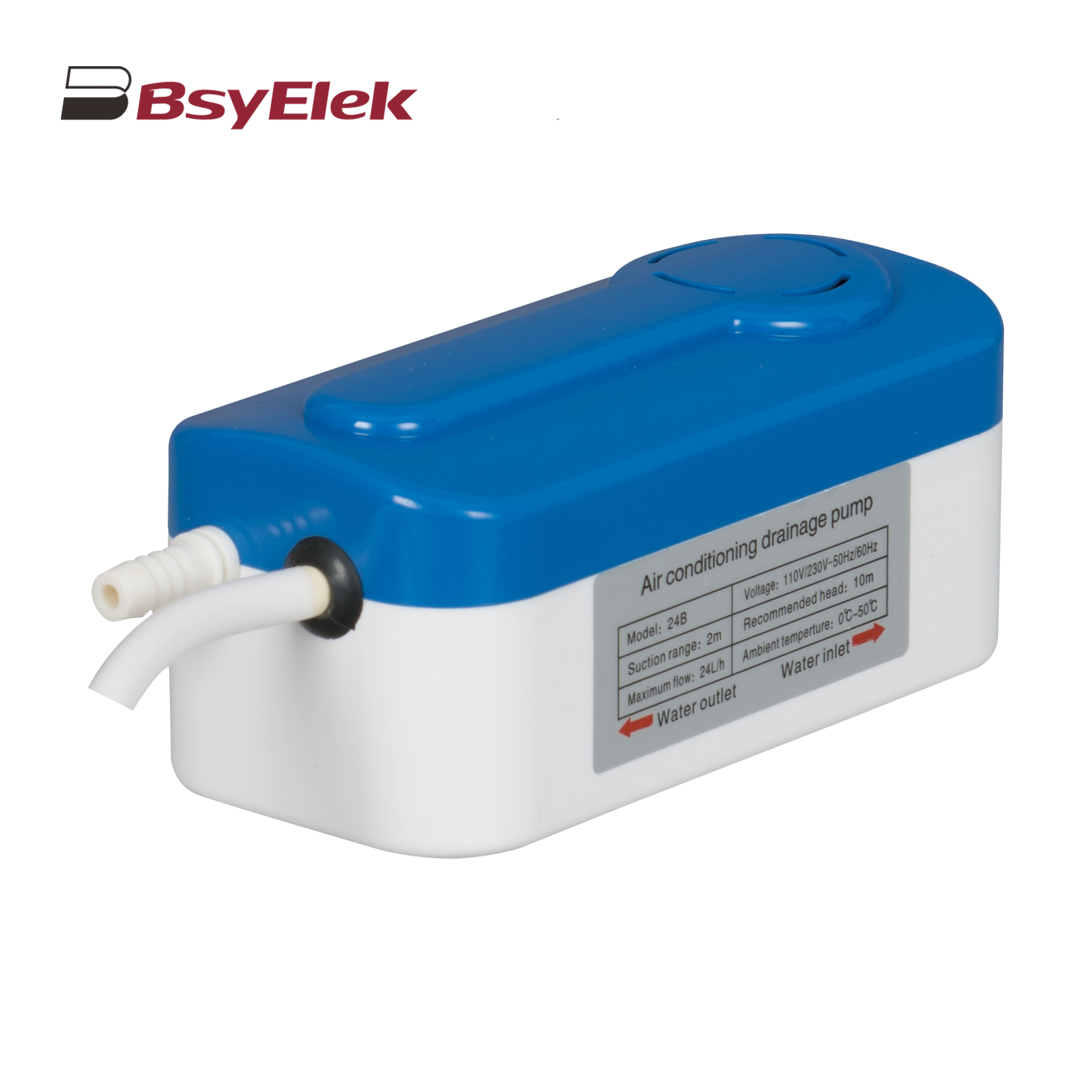
BY-24B/40B 10M Split Type Drainage Pump
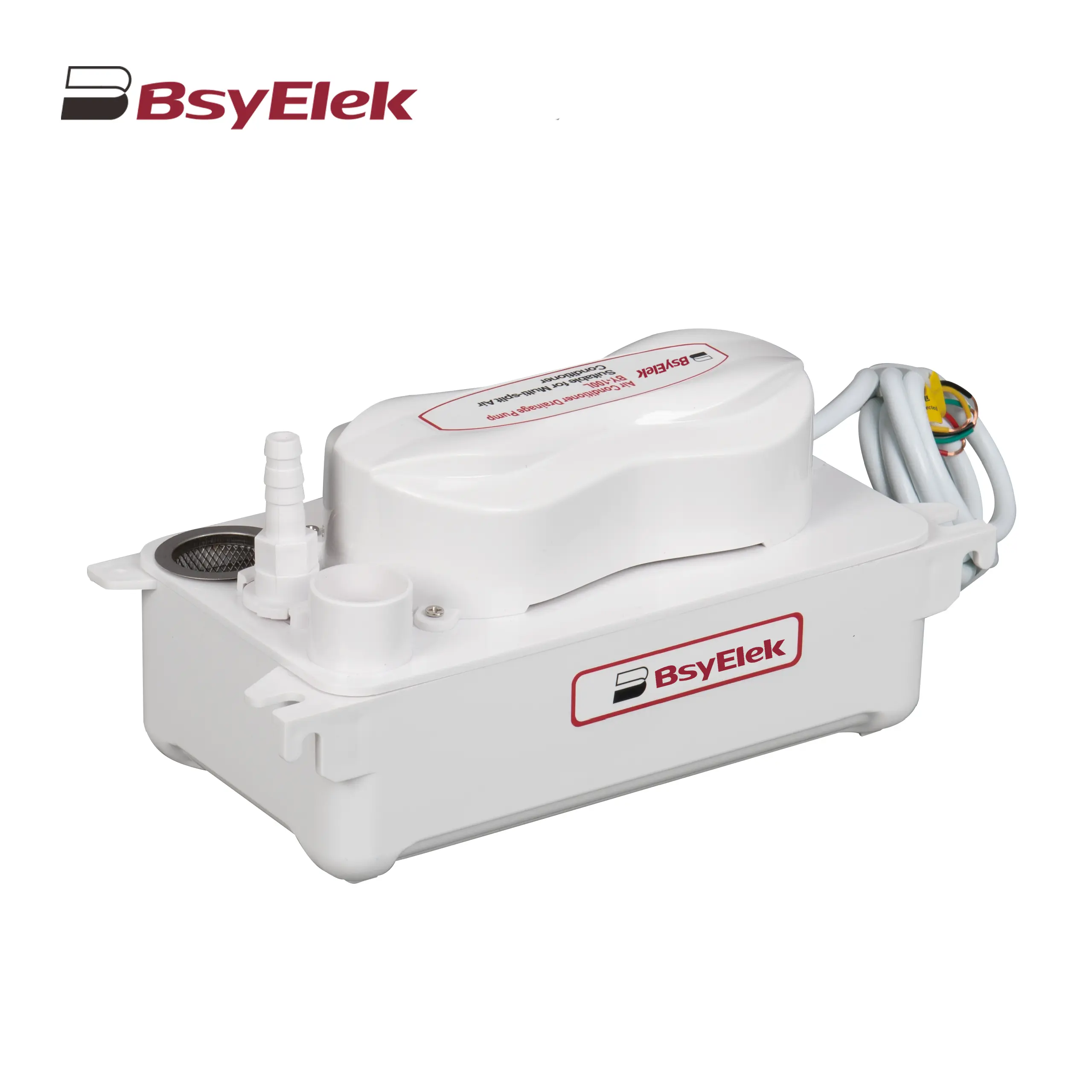
BY-100L 2M Drainage Pump of Air Conditioner
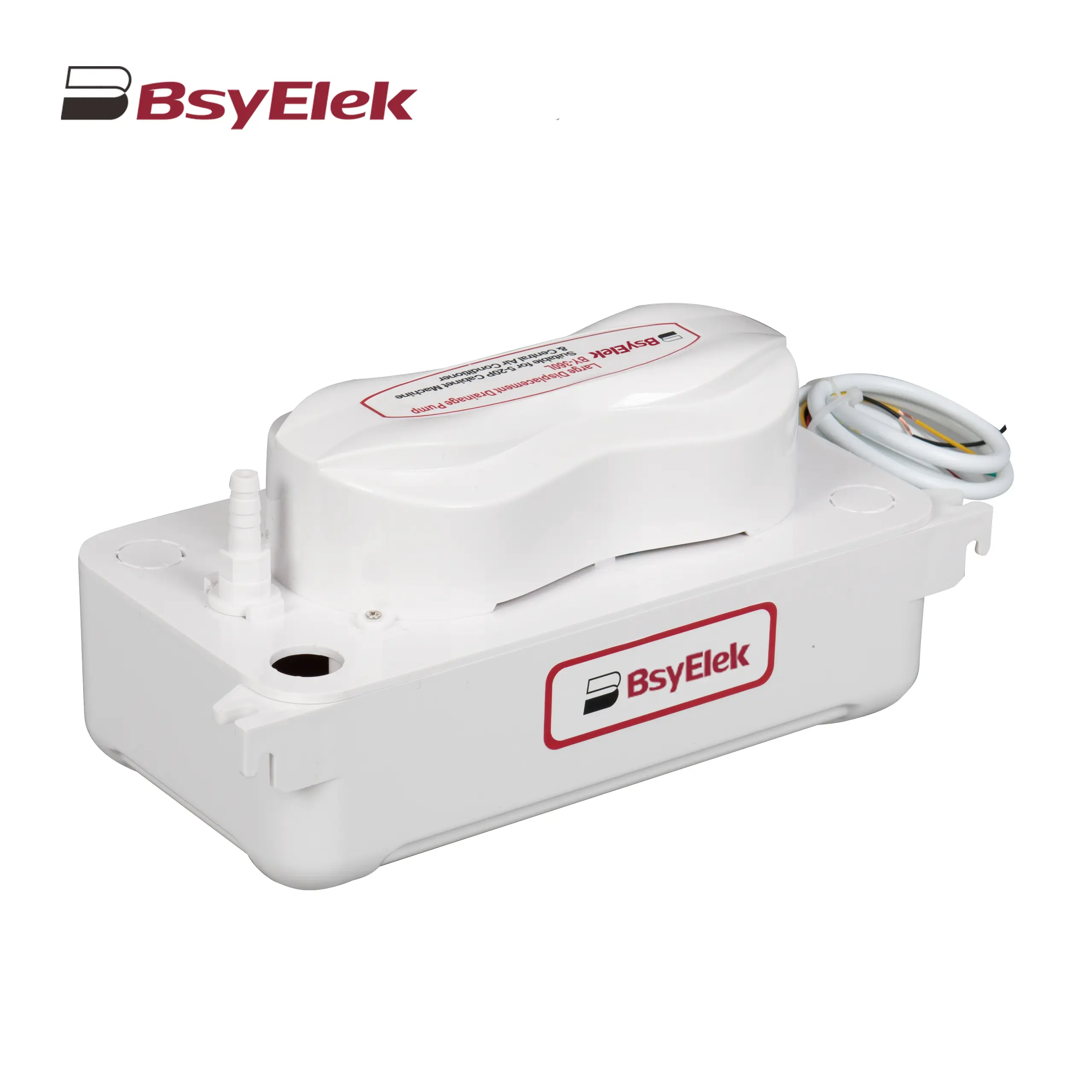
BY-360L 6M Large Displacement Drainage Pump
BY-24C/40C 10M Corner Drainage Pump
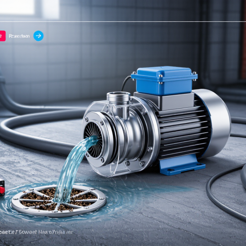
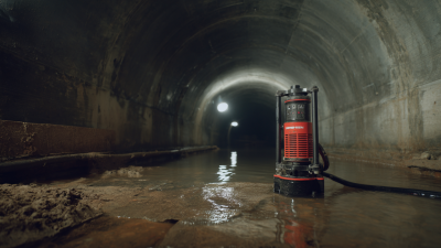
A Drainage Pump is a practical machine for moving unwanted water away from basements, construction sites, gardens, and wastewater systems. It usually combines an electric motor, impeller, casing, intake screen, and discharge pipe. When powered, the motor spins the impeller. The rotating blades create pressure, drawing water through the inlet and pushing it toward a higher or safer outlet. A float switch may start the pump automatically when water reaches a set level. Small details matter. A blocked screen can stop the system quickly.
The need is larger than many property owners realize. The WHO and UNICEF Joint Monitoring Programme reported that 3.5 billion people lacked safely managed sanitation in 2022. UN-Water’s World Water Development Report 2024 also identifies flooding, urban growth, and aging infrastructure as growing water-management pressures. These figures do not measure Drainage Pump sales directly. However, they show why reliable water removal deserves serious engineering attention. Market reports from Grand View Research and Fortune Business Insights also describe steady global demand for water and wastewater pumps, although their estimates differ by scope and methodology.
Pump specialist Lev Nelik explains the operating principle simply: “A pump transfers energy to a liquid.” That energy becomes flow and pressure. Yet the explanation is not complete. Pump performance changes with pipe length, elevation, debris, liquid viscosity, and power quality. This guide examines those variables clearly, while acknowledging one uncomfortable truth: correct installation often matters as much as the pump itself.
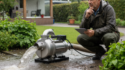
A drainage pump removes unwanted water from basements, trenches, tanks, and flooded work areas. It draws water through an inlet and sends it through a discharge pipe. Inside the casing, a motor turns an impeller. The impeller increases water velocity, while the casing changes that velocity into pressure. This pressure moves water against elevation and pipe resistance. The process is simple, but site conditions matter.
Typical drainage pump capacity ranges from 1 to 1,000 m³/h. Small pumps suit seepage, pits, and household drainage. Larger systems handle quarries, tunnels, stormwater reservoirs, and industrial sites. Working head commonly ranges from 5 to 100 m. A 5 m head may fit a shallow transfer route. A 100 m head requires stronger pressure and careful pipe design. Flow and head are connected. As head rises, available flow usually falls. Pipe friction, bends, valves, and dirty water reduce performance further.
Field technicians check the water depth, solids, distance, and elevation before choosing a pump. A coarse screen can protect the impeller from stones and debris. Screens clog quickly, though. That detail is often underestimated. A pump rated at 100 m³/h may deliver much less through a long, narrow hose. Measuring discharge on site gives more reliable evidence than reading a catalogue alone. Selection is rarely perfect on the first attempt. Recheck the actual flow after installation.
What Is a Drainage Pump and How Does It Work?
Core Components: Motors, Impellers, Casings, Seals, and IP68 Protection
A drainage pump removes unwanted water from basements, construction areas, tanks, and shallow pits. Its motor converts electrical energy into rotation. That rotation drives the impeller, which accelerates water through the casing. The casing then guides flow toward the discharge pipe and helps control pressure. Small details matter. A partially blocked inlet can reduce output quickly.
The impeller’s shape affects flow rate, pressure, and tolerance for suspended particles. Open impellers usually handle debris better, while closed designs can deliver stronger pressure with cleaner water. The casing must resist corrosion and withstand vibration. Around the rotating shaft, mechanical seals prevent water from reaching the motor. Worn seals may allow gradual leakage before a complete failure appears. That delay can mislead operators.
IP68 protection means the pump enclosure is dust-tight and suitable for continuous immersion under specified conditions. It does not mean unlimited depth, time, or chemical resistance. Always check the manufacturer’s test limits, cable condition, and installation instructions. In practical inspections, technicians should clean the inlet, examine the seal area, and test the float switch. Pumps are not maintenance-free. Even a well-designed unit may struggle when the discharge hose is too narrow, the lift is excessive, or gritty water enters continuously. More capacity is not always better.
| Component or Feature | Primary Function | How It Works | Typical Materials | Common Technical Data | Practical Considerations |
|---|---|---|---|---|---|
| Electric Motor | Provides the rotational power required to move water. | Electrical energy creates a rotating magnetic field that turns the motor shaft and attached impeller. | Copper windings, insulated steel laminations, stainless steel or carbon-steel shaft. | Typical power: 0.25–7.5 kW for many portable drainage pumps; single-phase or three-phase supply. | Motor selection depends on required flow, head, voltage, duty cycle, and available electrical supply. Thermal overload protection helps prevent damage caused by overheating. |
| Impeller | Converts motor rotation into water flow and pressure. | Curved vanes accelerate water outward by centrifugal force. The resulting velocity is converted into pressure inside the casing. | Cast iron, stainless steel, engineered thermoplastic, or abrasion-resistant alloy. | Typical styles: vortex, open, semi-open, or channel impellers; solids passage may range from approximately 10 to 75 mm depending on design. | Vortex impellers provide good clog resistance. Open and channel impellers can offer higher hydraulic efficiency but may require better control of solids and fibrous debris. |
| Pump Casing | Contains the rotating hydraulic parts and directs discharged water to the outlet. | The casing forms a controlled flow path around the impeller and changes water velocity into useful discharge pressure. | Cast iron, stainless steel, aluminum, or reinforced polymer. | Common discharge sizes: approximately 25–150 mm; operating head often ranges from 5 to 50 m, depending on pump design. | A larger discharge passage can reduce blockage risk. Casing material should match the water chemistry, temperature, and expected abrasion level. |
| Mechanical Seal | Prevents water from entering the motor compartment along the rotating shaft. | Two precision-machined seal faces remain pressed together while the shaft rotates, creating a dynamic water barrier. | Silicon carbide, ceramic, carbon, stainless steel, and elastomers such as NBR or EPDM. | Typical arrangement: single or tandem mechanical seals; seal choice depends on pressure, temperature, abrasives, and chemical exposure. | Running a pump dry can overheat and damage the seal faces. Abrasive sand, grit, and incompatible chemicals can significantly reduce seal life. |
| Shaft and Bearings | Transfers torque from the motor to the impeller and maintains accurate rotation. | Bearings support radial and axial loads while the shaft transmits motor torque through the sealed pump section. | Stainless steel or hardened steel shaft; sealed rolling-element bearings. | Key requirements: corrosion resistance, correct alignment, adequate lubrication, and compatibility with the impeller load. | Unusual vibration, noise, or shaft play may indicate bearing wear, imbalance, cavitation, or a partially blocked hydraulic passage. |
| Motor Housing | Protects electrical windings and supports the motor and pump assembly. | The housing provides mechanical protection and transfers heat away from internal components, often through the surrounding liquid or an external surface. | Stainless steel, cast iron, aluminum, or impact-resistant polymer. | Design factors: corrosion resistance, heat dissipation, pressure resistance, and cable-entry protection. | Housing temperature and cooling conditions must remain within the manufacturer’s operating limits, especially during extended operation or low-water conditions. |
| IP68 Protection | Indicates a high level of protection against dust and continuous water immersion under specified conditions. | The enclosure is dust-tight and designed for immersion beyond 1 metre, with the exact depth and duration defined by the equipment manufacturer or test specification. | Sealed enclosure, cable gland, gaskets, O-rings, and corrosion-resistant fasteners. | Meaning: “6” denotes dust-tight protection; “8” denotes protection against continuous immersion under stated conditions. | IP68 is not a universal operating-depth rating. Cable joints, plugs, controls, and accessories must have suitable protection ratings as well. |
| Float Switch or Level Sensor | Starts or stops the pump according to the liquid level. | A floating mechanism or electronic sensor detects a preset water level and operates the control circuit. | Polypropylene, polyethylene, PVC, stainless steel, and sealed electrical contacts. | Control type: automatic level control with adjustable start and stop points on compatible installations. | The sensor needs sufficient free movement. Debris, narrow pits, or tangled cables can prevent reliable switching and cause dry running or overflow. |
| Strainer or Inlet Screen | Reduces the chance of large debris entering the impeller and casing. | Perforations or a shaped inlet allow water to enter while limiting the passage of oversized solids. | Stainless steel, coated steel, cast iron, or reinforced polymer. | Typical role: supports the pump’s specified solids-handling capability; opening size must not restrict the rated flow. | Regular cleaning is important. A blocked inlet can reduce flow, increase motor load, and contribute to overheating or cavitation. |
| Discharge Pipe and Check Valve | Conveys pumped water away from the sump and helps prevent reverse flow. | The discharge pipe carries water from the pump outlet; a check valve closes when the pump stops to limit backflow and water hammer. | PVC, HDPE, stainless steel, ductile iron, or reinforced flexible hose. | Design principle: pipe diameter and length directly affect friction losses, total dynamic head, and delivered flow. | Avoid sharp bends and undersized piping. The check valve should be suitable for the fluid, pressure, solids content, and installation orientation. |
| Hydraulic Performance | Describes the relationship between flow rate, head, power consumption, and efficiency. | As discharge head increases, the available flow generally decreases. The operating point is where the pump curve intersects the system curve. | Not applicable; performance is determined by pump geometry and system design. | Typical portable drainage range: approximately 5–100 m³/h flow and 5–40 m head, depending on pump size and application. | Use the rated performance curve rather than maximum free-flow figures. Total dynamic head includes elevation, pipe friction, fittings, and outlet pressure. |
| Typical Applications | Removes unwanted water from low-lying or flooded areas. | The pump is placed in a sump, pit, tank, trench, basement, or construction area and transfers water to a safe discharge location. | Application-dependent. | Examples: basement drainage, stormwater removal, dewatering, tank emptying, utility pits, and wastewater transfer. | Confirm water temperature, pH, solids size, fiber content, electrical supply, immersion depth, and required duty before selecting a pump. |
Note: The technical ranges shown are general industry ranges for drainage pump designs. Actual performance, immersion limits, materials, and operating conditions vary by pump construction and application.
What Is a Drainage Pump and How Does It Work?
How It Works: From Water Intake to Discharge Through Pressure Generation
A drainage pump removes unwanted water from basements, pits, tanks, and construction areas. Its operation begins at the intake opening, where water enters through a screened inlet. The screen blocks stones, leaves, and other debris that could damage internal parts. However, a blocked screen can reduce flow sharply. This small detail is often overlooked.
Inside the casing, an electric motor rotates an impeller. Curved blades accelerate the incoming water and create lower pressure near the center. Atmospheric pressure then pushes more water toward the impeller. The rotating water gains velocity and pressure before moving into the discharge passage. The casing changes much of that velocity into useful pressure.
A discharge pipe carries water to a safer, higher, or distant location. The pump must generate enough pressure to overcome elevation, pipe friction, bends, and outlet resistance. This total requirement is called pump head. A check valve can prevent discharged water from flowing backward when the motor stops. A float switch may start or stop the pump as the water level changes.
In practical installations, poor pipe sizing can cause disappointing performance. A pump may run continuously while moving little water. Air leaks, excessive lift, and dirty impellers create similar symptoms. Cavitation is another concern, especially when the intake supply is restricted. It produces noise and vibration. Technicians should inspect connections, measure flow, and verify actual head rather than trusting appearance alone.
What Is a Drainage Pump and How Does It Work?
Pump Types Compared: Submersible, Centrifugal, Vortex, and Diaphragm Designs
A drainage pump removes collected water from basements, trenches, tanks, and construction sites. It converts motor power into pressure and flow. The right design depends on water depth, solids, discharge distance, and operating time. The International Energy Agency reports that electric motor systems use about half of global electricity. Pump efficiency is not a minor detail.
Submersible pumps operate below the water surface. Their sealed motors suit flooded pits and emergency drainage. Centrifugal pumps move relatively clean water efficiently through rotating impellers. They work well for long discharge runs, but abrasive solids can damage their passages. Vortex pumps create a recessed impeller flow path. This reduces clogging when leaves, sludge, or suspended solids enter the intake. Flow may drop, though. Diaphragm pumps use a flexible membrane and check valves. They handle air, thicker fluids, and intermittent suction better than many centrifugal designs.
The U.S. Department of Energy states that pumping systems can represent roughly 25% of industrial motor electricity use. Correct sizing can therefore reduce wasted energy. In practice, a submersible unit is often the simplest choice for a deep sump. A vortex model may be safer near debris. A diaphragm pump can be useful where priming is unreliable. These categories overlap, and real sites are rarely neat. I have seen specifications fail because engineers compared flow rates without checking solids size, head pressure, or cable protection. The best selection follows measured conditions, not a catalogue label.
Drainage pumps remove unwanted water from areas such as basements, construction sites, tanks, and flooded ground. The chart compares representative operating-head ranges for four common pump designs. Actual performance depends on pump size, motor power, pipework, fluid properties, and solids content.
How the designs work: Submersible pumps operate while immersed in water and are commonly used for direct water removal. Centrifugal pumps use a rotating impeller to convert motor energy into water flow and pressure. Vortex pumps create a swirling flow that reduces direct contact between solids and the impeller, making them suitable for wastewater containing debris. Diaphragm pumps use a flexible membrane and check valves to move liquid and can handle air or intermittently dry conditions better than many centrifugal designs.
The plotted values are representative drainage-service ranges in metres of head, provided for general comparison rather than as equipment specifications.
A drainage pump removes unwanted water from basements, construction pits, tanks, and flooded areas. Its motor spins an impeller inside a sealed housing. The impeller creates pressure and pushes water through the discharge pipe. A float switch may start the pump when water rises. It can also stop the unit automatically.
Power strongly affects pumping performance. Small 0.5 kW models suit light drainage and limited water volumes. Larger units, reaching 30 kW, handle deeper sites and longer discharge routes. However, more power does not always mean better results. Pipe length, lift height, bends, and inlet conditions can reduce actual flow. A neat specification can still mislead.
Solids handling is equally important. Pumps rated for 20–50 mm particles are better suited to muddy water, leaves, and small stones. The selected passage should match the site, not just the average debris size. I have seen operators choose narrow passages because the pump looked more efficient. Blockages followed.
Efficiency depends on hydraulic design, motor loading, and maintenance. A clean intake screen helps, but excessive screening can restrict flow.
Check power consumption during operation, not only in catalog conditions. Small compromises often become expensive.
Regular inspection of seals, cables, impellers, and discharge connections improves reliability and reveals problems before failure.