| Surge Protective Device Selection |
| SPD Type 1 |
Installation position |
Service entrance or line side of the main disconnect; intended for systems where external lightning current may enter the installation. |
Use only where the equipment is suitable for the service-entrance arrangement and is coordinated with the system grounding and overcurrent protection. |
| SPD Type 2 |
Installation position |
Load side of the main disconnect, commonly installed in a main distribution board or panelboard. |
Often the primary choice for protecting commercial, industrial, and residential distribution equipment against conducted transient overvoltage. |
| SPD Type 3 |
Installation position |
Point-of-use protection installed near sensitive equipment, normally downstream from Type 1 or Type 2 protection. |
Use for computers, control systems, communication equipment, and other devices requiring supplementary protection. Keep connecting leads short. |
| Nominal discharge current (In) |
Repeated surge-current capability |
For many low-voltage installations, a practical selection range is 5–20 kA per mode, depending on exposure and applicable standard. |
Choose a value appropriate to the expected surge environment. A higher In rating does not automatically mean a lower let-through voltage. |
| Maximum continuous operating voltage (Uc or MCOV) |
Continuous voltage withstand |
Select a device with an MCOV suitable for the nominal system voltage, earthing arrangement, and the maximum expected temporary overvoltage. |
Do not select MCOV solely from the nominal voltage. Confirm line-to-neutral, line-to-line, and neutral-to-earth voltage conditions before installation. |
| Voltage protection level (Up or VPR) |
Residual or let-through voltage |
Use the lowest practical protection level that remains compatible with the system voltage and equipment insulation coordination. |
The protection level should be below the impulse withstand level of the equipment being protected, with appropriate wiring and coordination. |
| Short-circuit current rating |
Fault-current withstand |
Use an SPD with a short-circuit rating equal to or greater than the available prospective fault current at the installation point. |
Verify the rating against the distribution-board calculation and install the specified backup overcurrent protective device where required. |
| Response time |
Transient response |
Many voltage-limiting SPDs respond in the nanosecond range, but response time alone is not a sufficient performance indicator. |
Prioritize MCOV, protection level, surge-current capability, safety certification, and installation quality over response-time marketing figures. |
| Installation Requirements |
| Connection conductors |
Lead length and routing |
Keep line, neutral, and protective-earth conductors as short and straight as practicable; avoid unnecessary loops and sharp bends. |
A commonly used design target is a total connecting-path length of approximately 0.5 m or less, where practical. Follow the applicable installation standard and manufacturer instructions. |
| Conductor size |
Thermal and fault-current capacity |
Use conductor sizes specified by the SPD instructions and local electrical code; commonly used copper conductors may range from 2.5 mm² to 16 mm² depending on the application. |
Do not reduce conductor size below the permitted value. Tighten terminals to the specified torque and verify that conductors are mechanically secure. |
| Grounding and bonding |
Discharge-current path |
The SPD must connect to a low-impedance protective-earth and bonding system. |
Never use a water pipe, gas pipe, isolated equipment chassis, or other unapproved path as the sole grounding conductor. |
| Backup overcurrent protection |
Coordination and safety |
Provide the fuse or circuit breaker specified for the SPD, unless the installation rules explicitly permit the existing upstream device. |
Confirm voltage rating, interrupting rating, conductor ampacity, and coordination with the distribution equipment before energizing. |
| System compatibility |
Electrical configuration |
Check single-phase or three-phase arrangement, number of conductors, earthing system, nominal frequency, and nominal voltage. |
Incorrect configuration can cause nuisance operation, premature failure, or unsafe continuous current through the SPD. |
| Environmental suitability |
Location and enclosure |
Use an enclosure and SPD rated for the installation environment, including temperature, humidity, dust, water exposure, and indoor or outdoor location. |
Install where inspection is possible and protect the device from mechanical damage, excessive heat, and condensation. |
| Testing and Verification |
| Visual inspection |
Service condition |
Check the status indicator, enclosure, terminals, labels, backup protection, and signs of overheating or physical damage. |
Perform during commissioning and at scheduled maintenance intervals. A failed indicator normally means the protection module must be replaced. |
| Voltage verification |
Correct operating voltage |
Measure the system voltage and confirm that it is within the SPD’s specified operating range. |
Use a properly rated, calibrated test instrument and follow electrical safe-work procedures. Do not test energized equipment unless qualified to do so. |
| Continuity and bonding checks |
Protective-earth path |
Verify continuity of the protective conductor and bonding connections using an approved method. |
Do not rely on a basic resistance reading as proof of surge performance; surge-current paths also depend on conductor length, routing, and inductance. |
| Insulation resistance testing |
Compatibility with the SPD |
Follow the SPD instructions before applying an insulation-resistance test voltage. |
Disconnect or isolate the SPD when required, because high-voltage insulation testers can damage voltage-limiting components or produce misleading results. |
| Remote alarm contact |
Condition monitoring |
Where provided, verify the normally open or normally closed alarm contact and its rated switching capacity. |
Connect only to a compatible monitoring circuit. Confirm that the alarm changes state when the protection module reaches its end-of-life condition. |
| Maintenance and Replacement |
| Routine inspection interval |
Inspection frequency |
Inspect at least annually, and more frequently in areas with frequent thunderstorms, switching events, contamination, or critical loads. |
Record inspection dates, indicator status, measured voltage, terminal condition, and any corrective action. |
| After a major surge event |
Post-event assessment |
Inspect the SPD and connected equipment after a nearby lightning strike, major switching event, or reported electrical abnormality. |
Replace the SPD if the indicator is failed, the enclosure is damaged, there is evidence of overheating, or the device has reached its end-of-life state. |
| Thermal or odor signs |
Safety warning |
Discoloration, melted plastic, cracking, smoke residue, unusual odor, or repeated tripping indicates a potentially unsafe condition. |
De-energize the affected circuit using safe procedures and have the installation examined by a qualified electrical professional. |
| Replaceable modules |
Serviceability |
Use a replacement module with the same electrical ratings, configuration, and compatibility requirements as the original module. |
Isolate all relevant sources, including alternate feeds and stored energy, before replacement. Recheck torque, wiring, indicator status, and enclosure integrity. |
| Documentation |
Asset and maintenance records |
Record SPD type, nominal system voltage, MCOV, protection level, In rating, installation location, inspection date, and replacement history. |
Maintain the records with the electrical drawings and risk assessment so future replacements can be selected correctly. |
| Overall selection principle |
Best SPD for an installation |
The best choice is the device that matches the system voltage and earthing arrangement, provides suitable surge-current capacity and protection level, and is correctly coordinated with upstream and downstream protection. |
Always verify the latest applicable electrical code, installation standard, product certification, and qualified-person requirements before purchase or installation. |



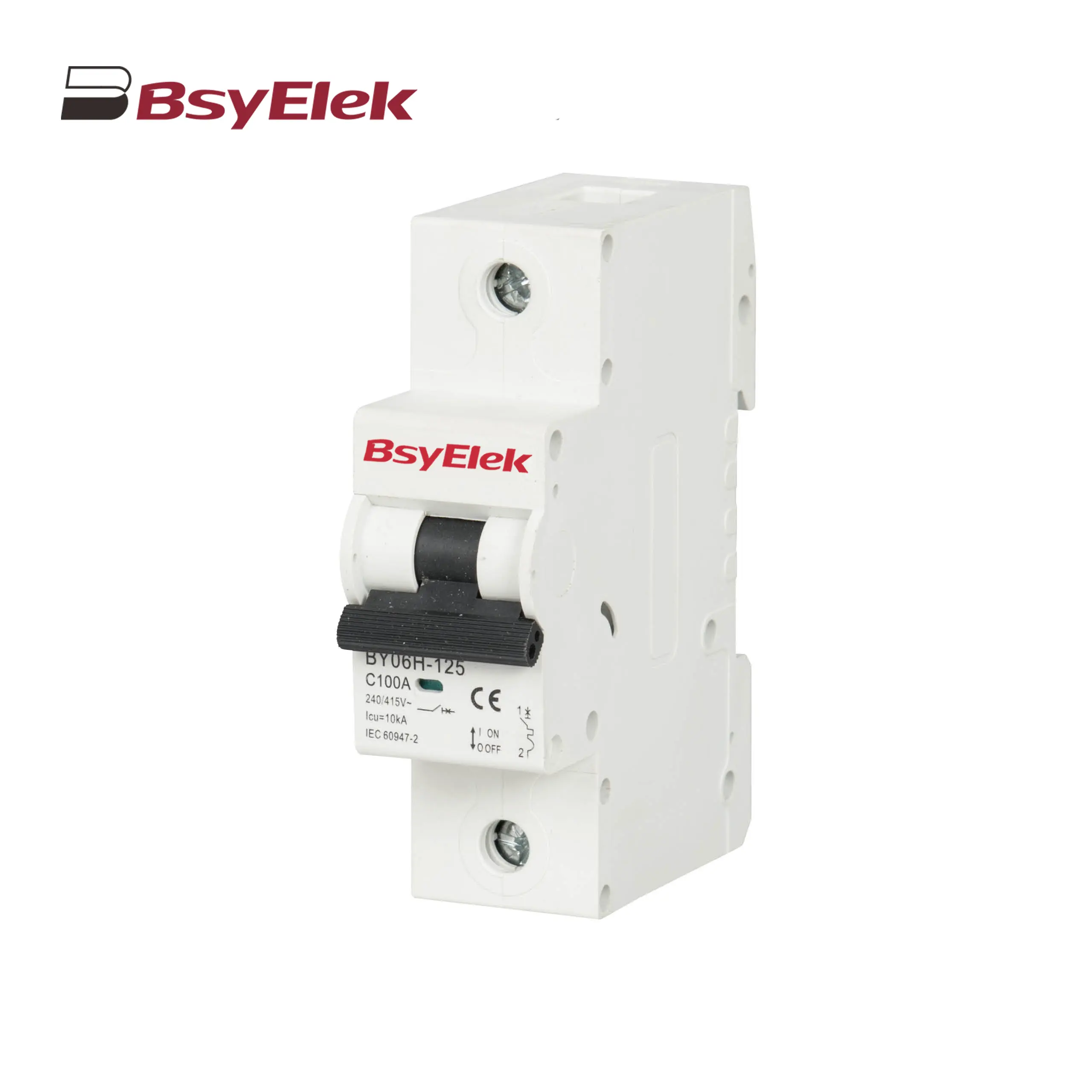 BY06H-125 MCB 10-15KA Miniature Circuit Breaker
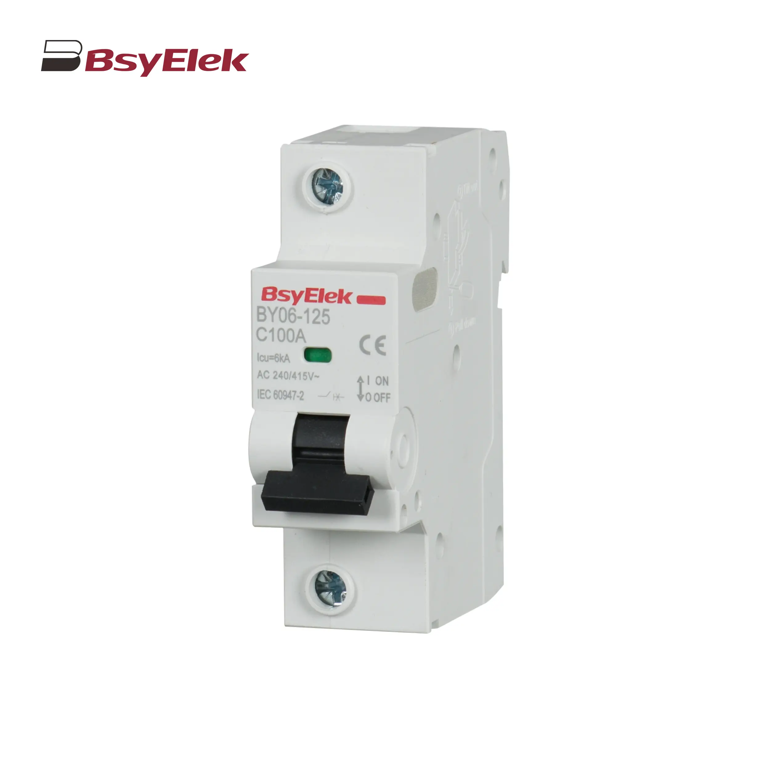 BY06-125 MCB 6KA Miniature Circuit Breaker
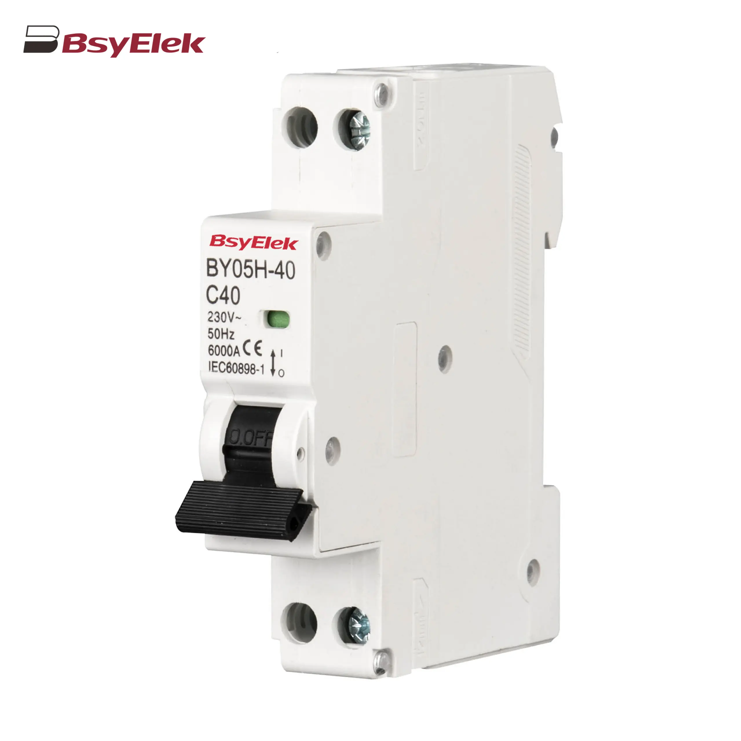 BY05H-40 MCB Single Modular 6KA Miniature Circuit Breaker
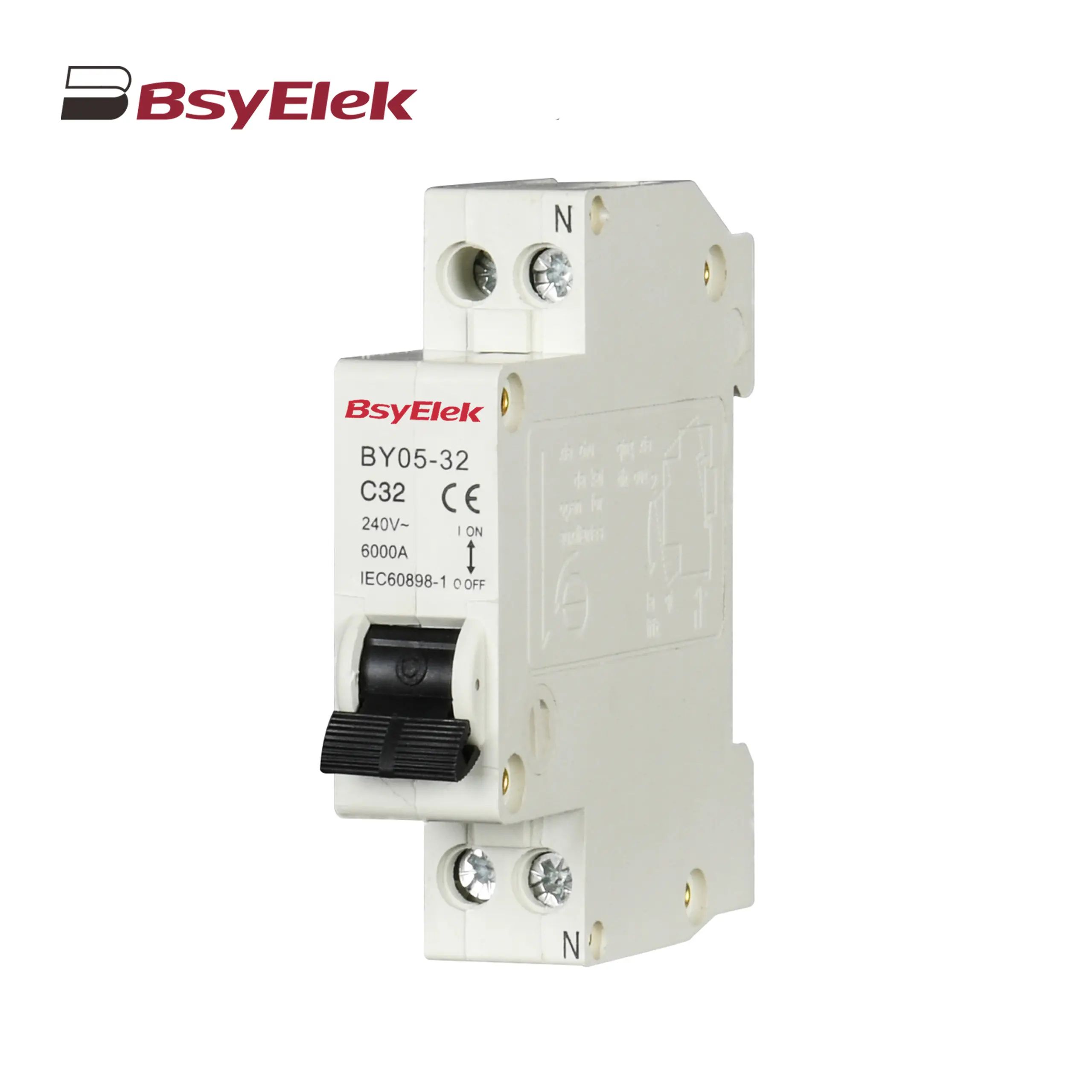 BY05-32 MCB Single Modular 3KA Miniature Circuit Breaker
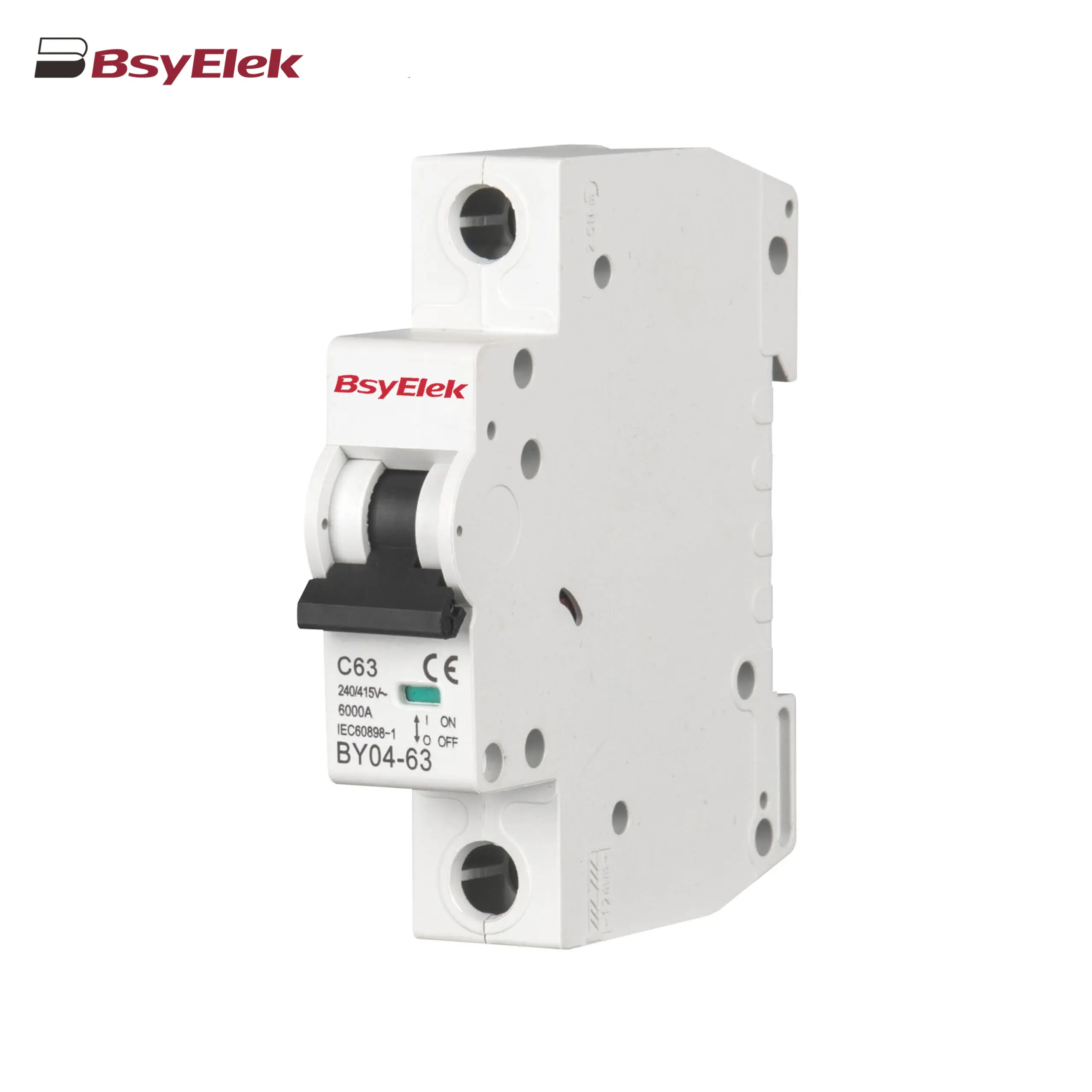 BY04-63 MCB 6-10KA Miniature Circuit Breaker
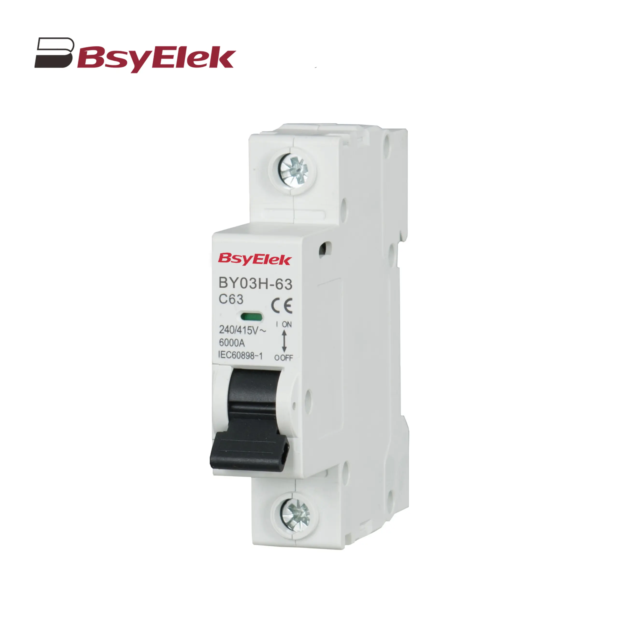 BY03H-63 MCB 6KA Miniature Circuit Breaker
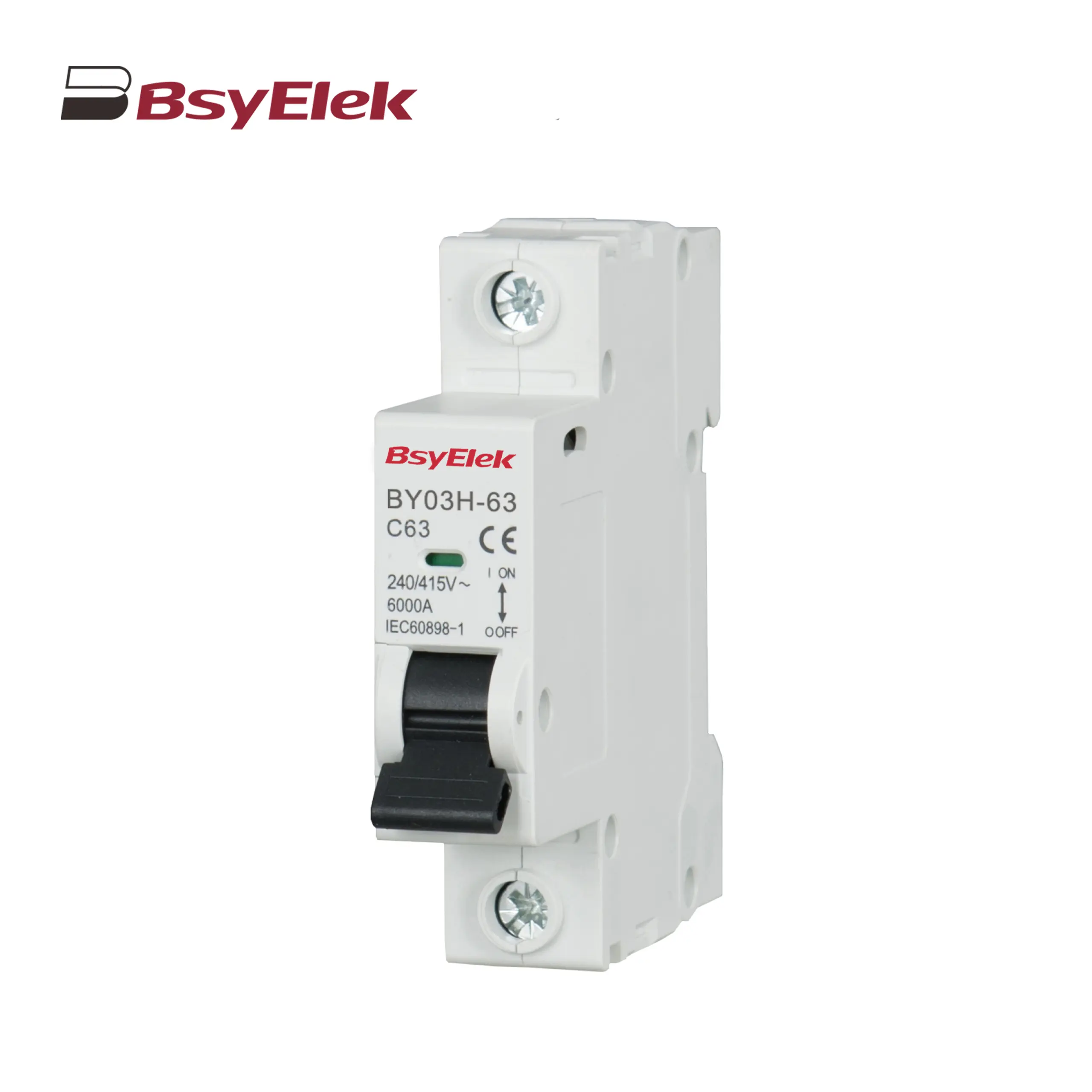 BY03-63 MCB 4.5KA Miniature Circuit Breaker
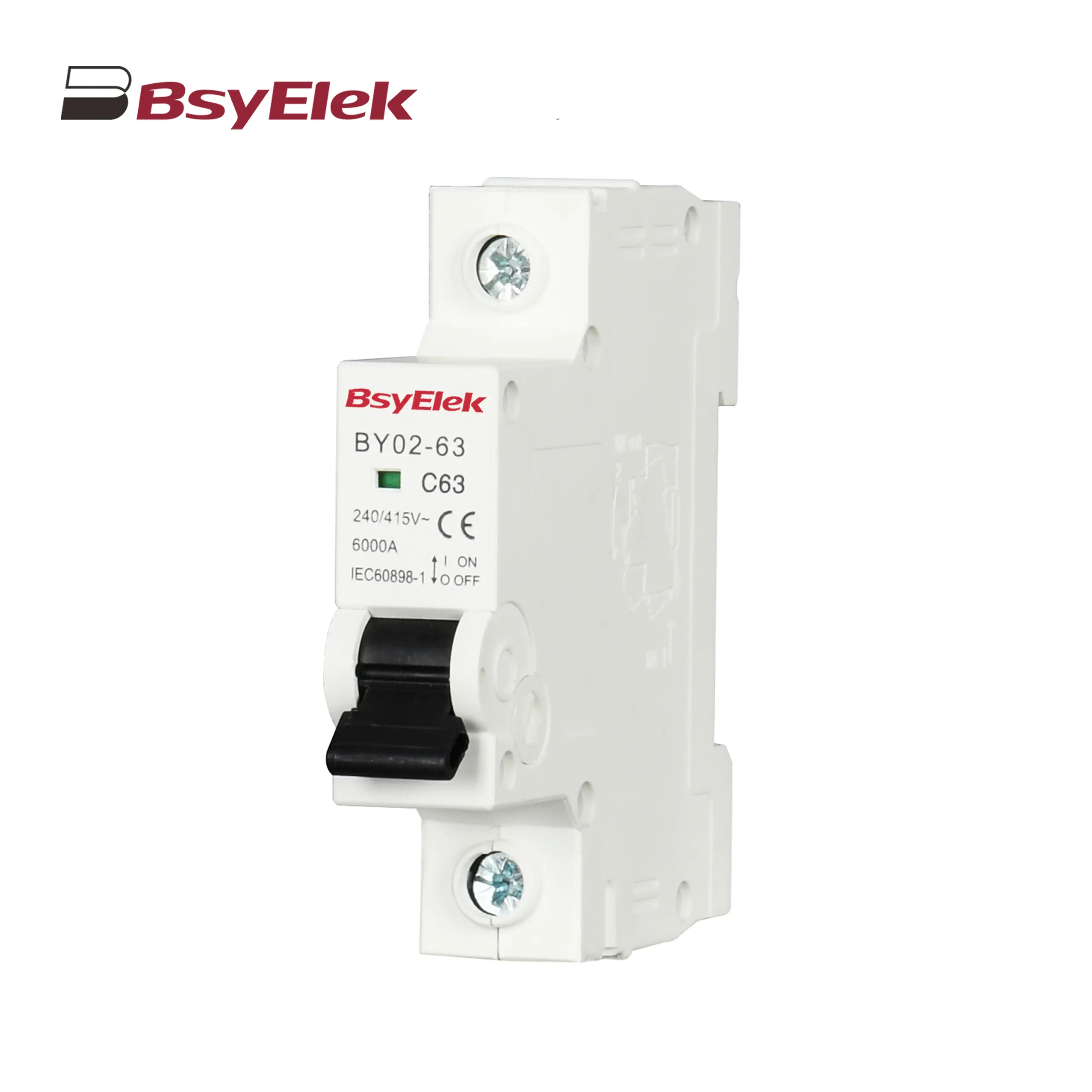 BY02-63 MCB 3kA Miniature Circuit Breaker
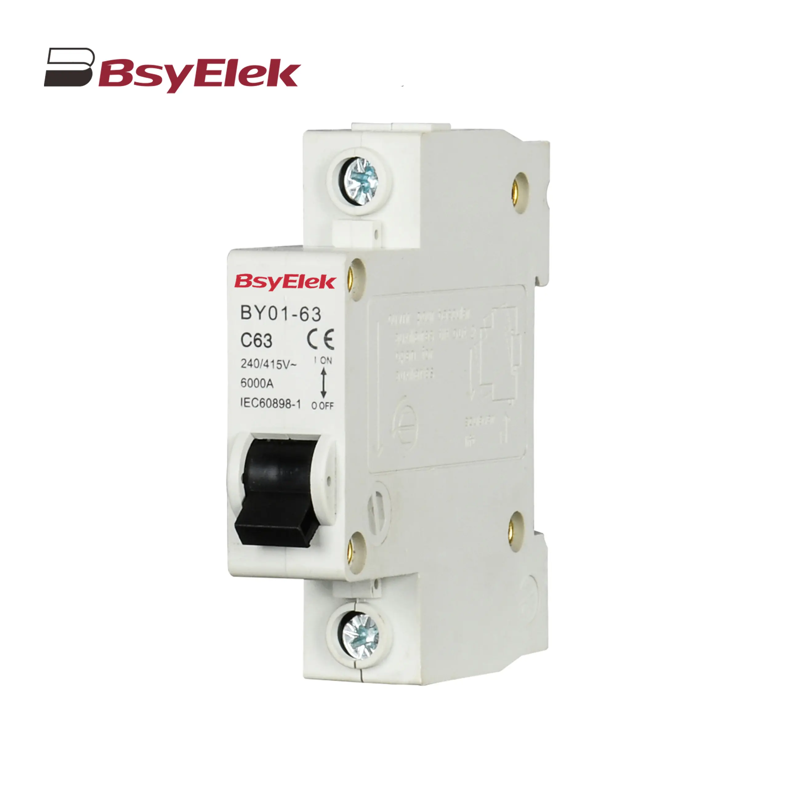 BY01-63 MCB 3kA Miniature Circuit Breaker
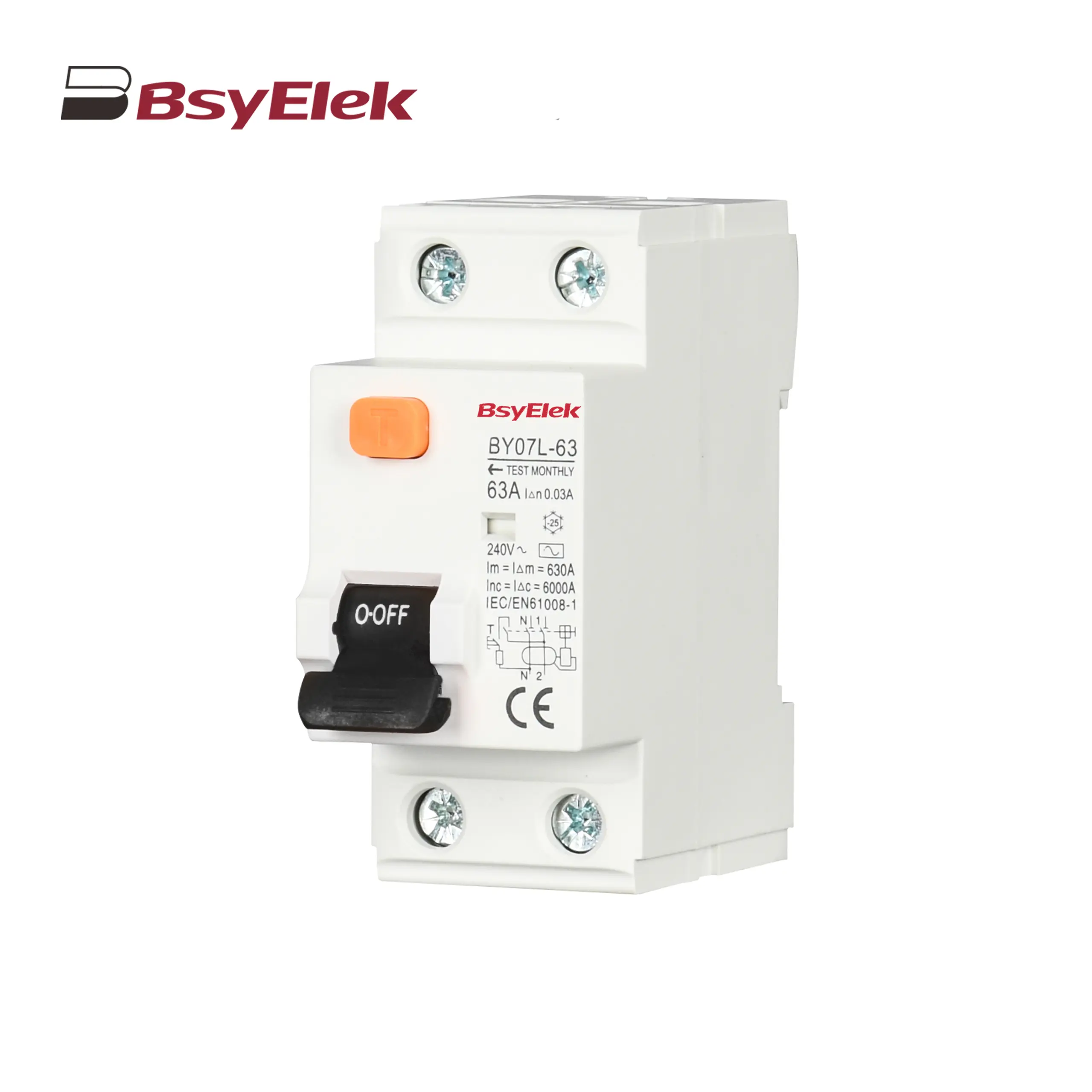 BY07L-63 RCCB 6KA Residual Current Circuit Breaker
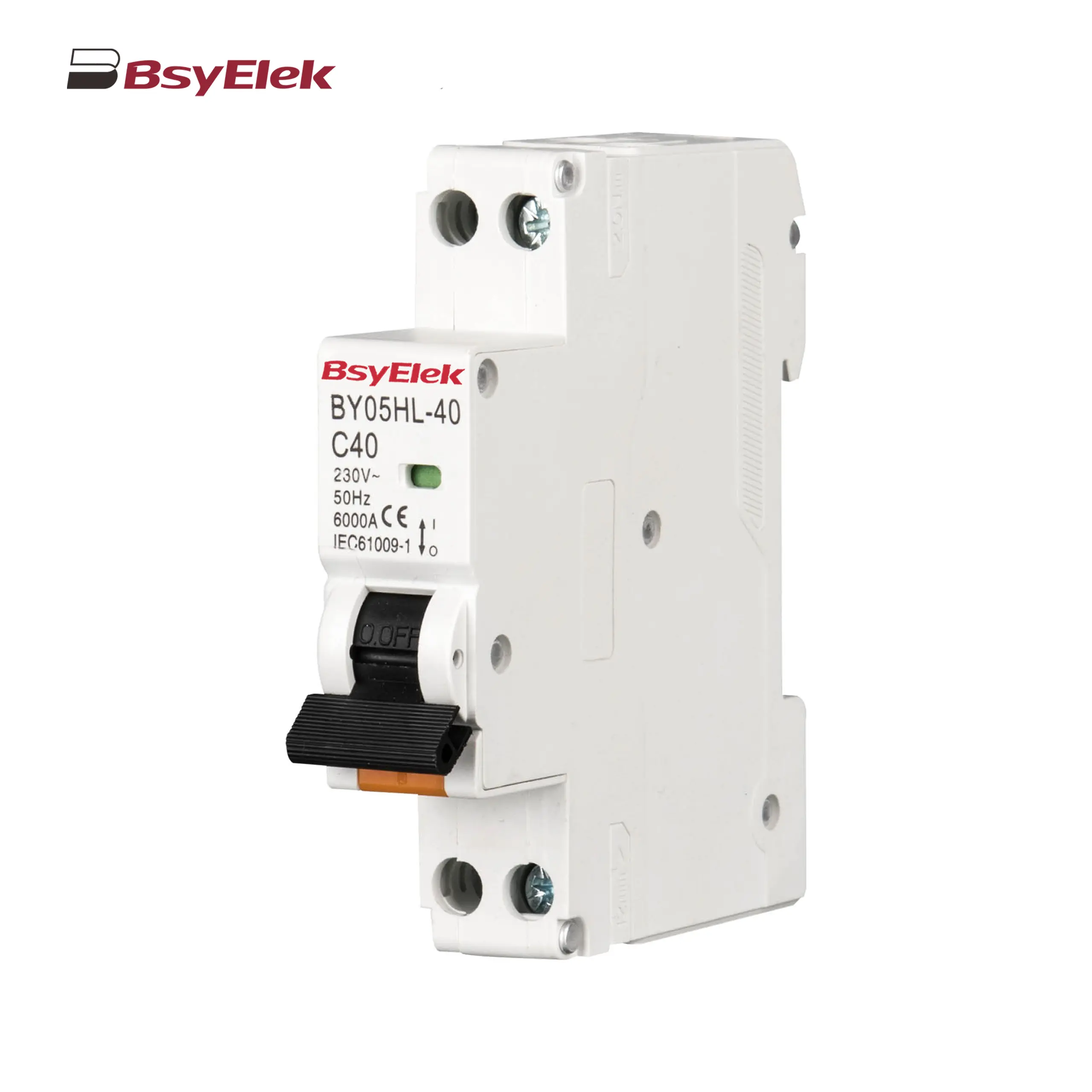 BY05HL-40 RCBO 6KA Residual Current Circuit Breaker with Over-current Protection
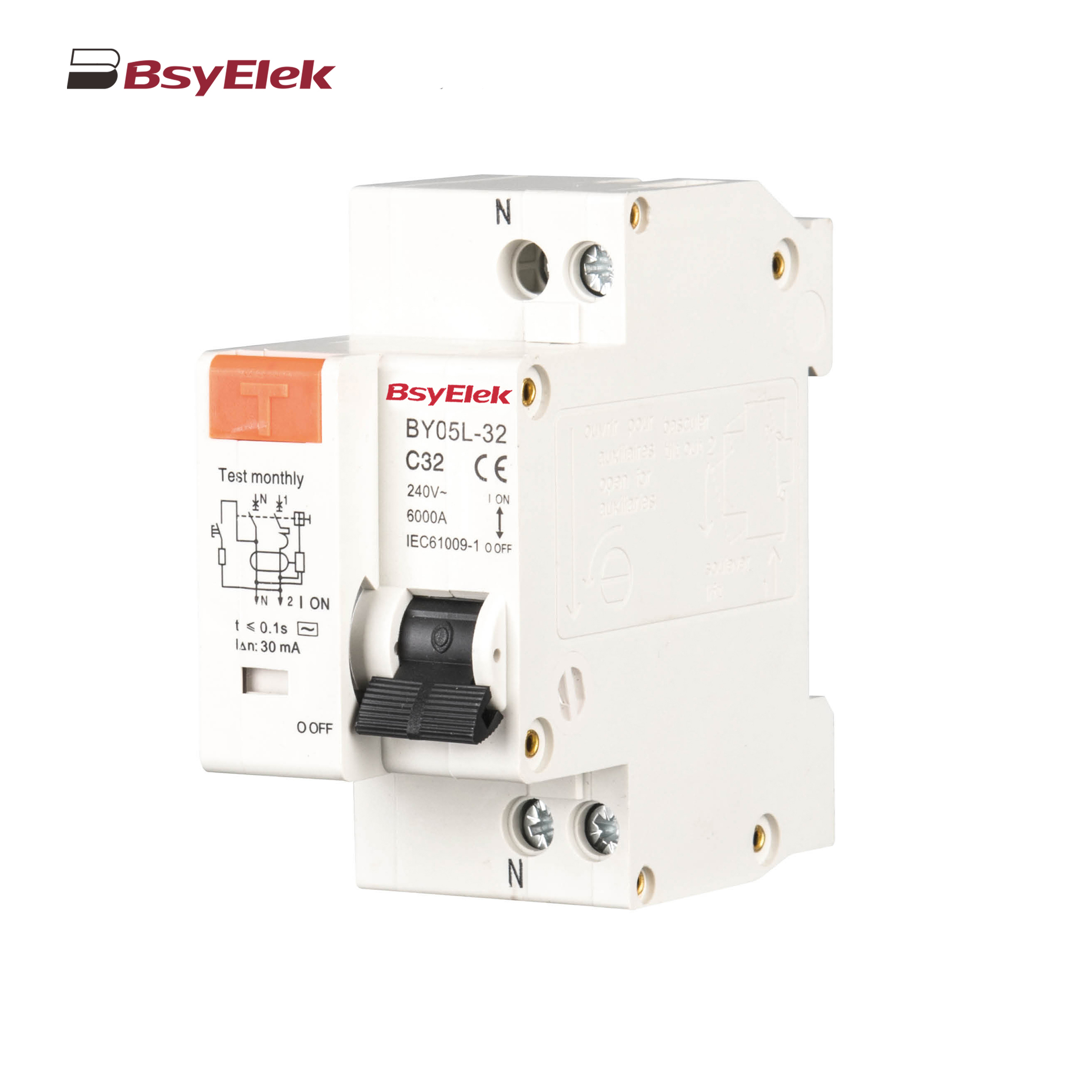 BY05L-32 RCBO 3KA Residual Current Circuit Breaker with Over-current Protection
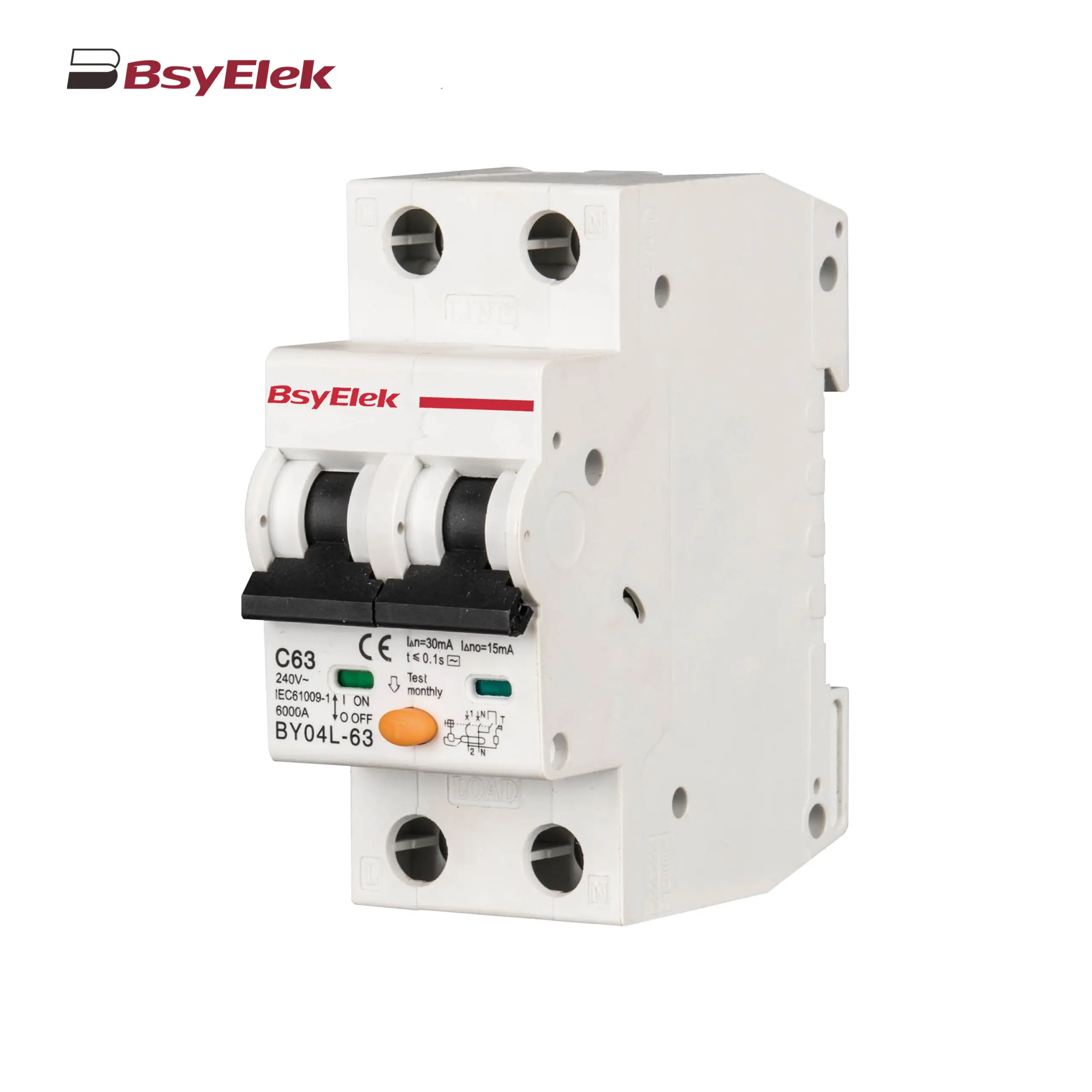 BY04L-63 RCBO 6KA Residual Current Circuit Breaker with Over-current Protection
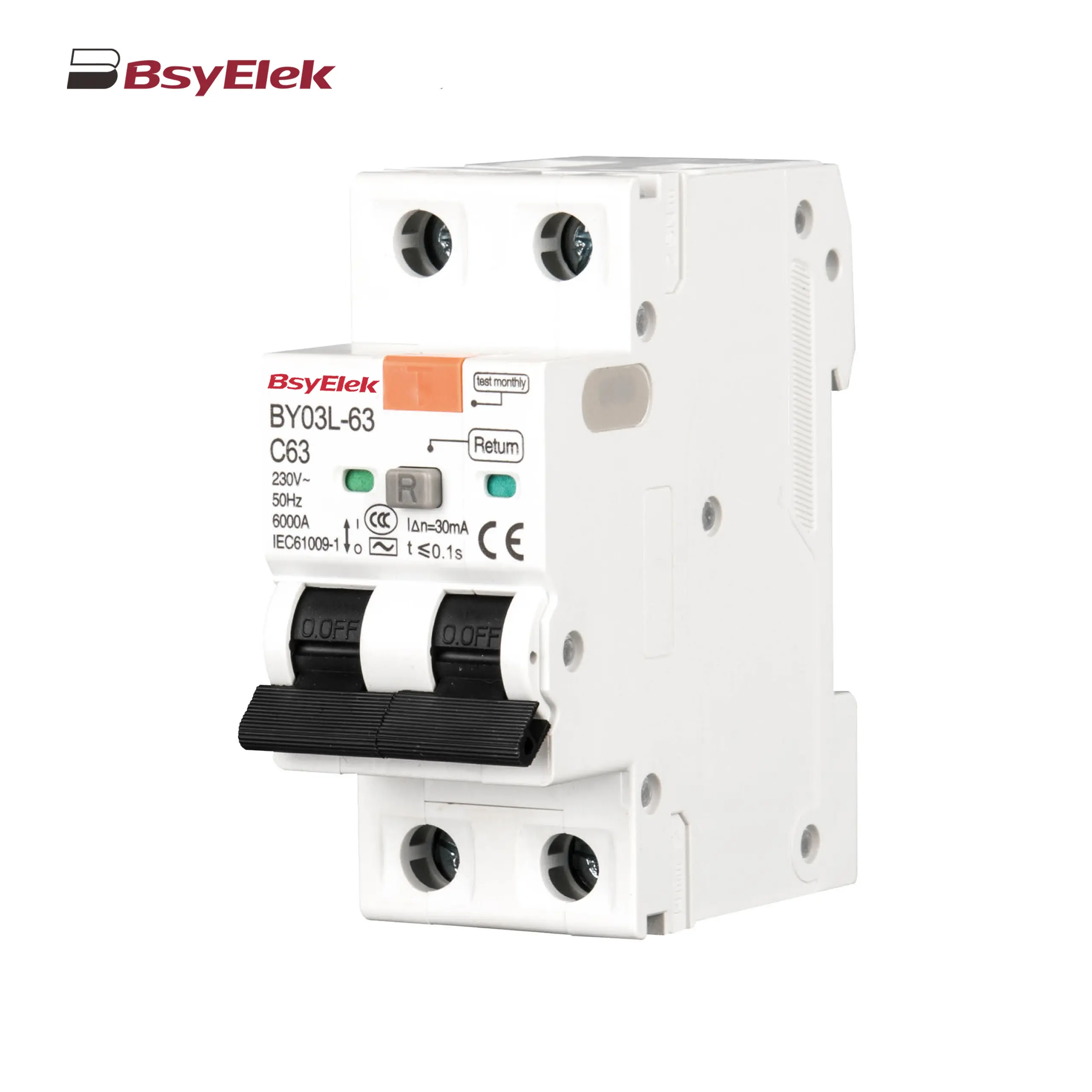 BY03L-63 RCBO 4.5KA Residual Current Circuit Breaker with Over-current Protection
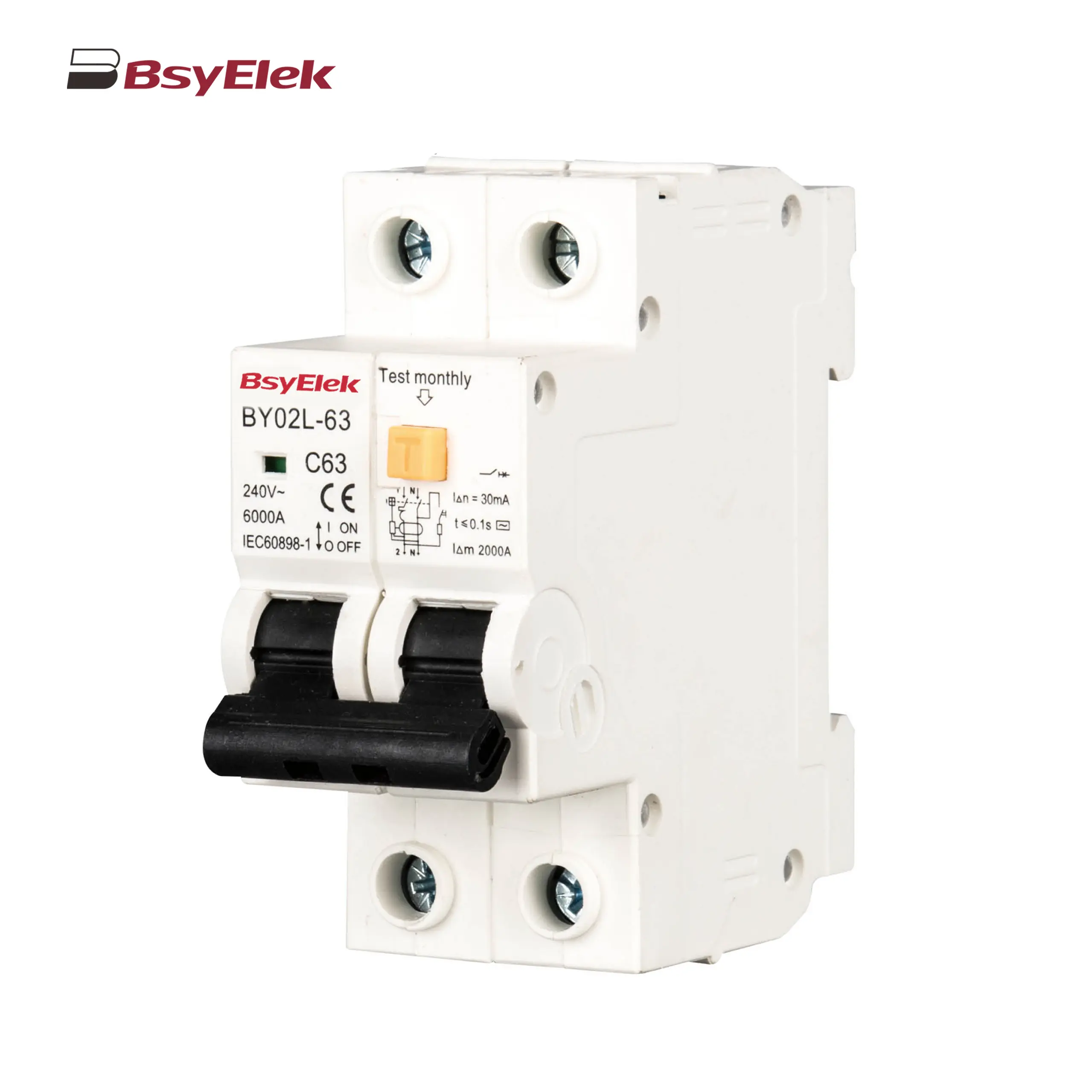 BY02L-63 RCBO 3KA Residual Current Circuit Breaker with Over-current Protection
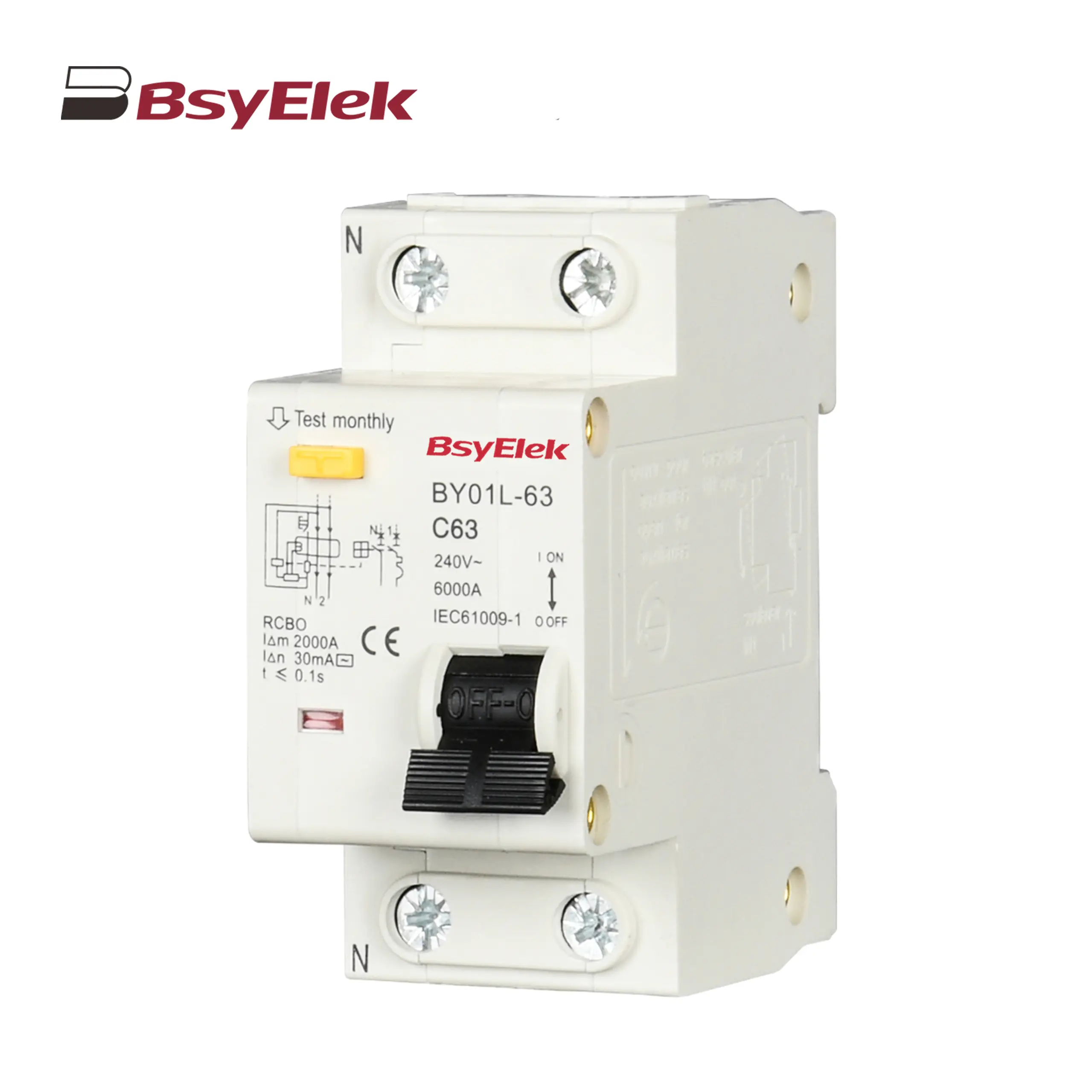 BY01L-63 RCBO 1P+N 3KA Residual Current Circuit Breaker with Over-current Protection
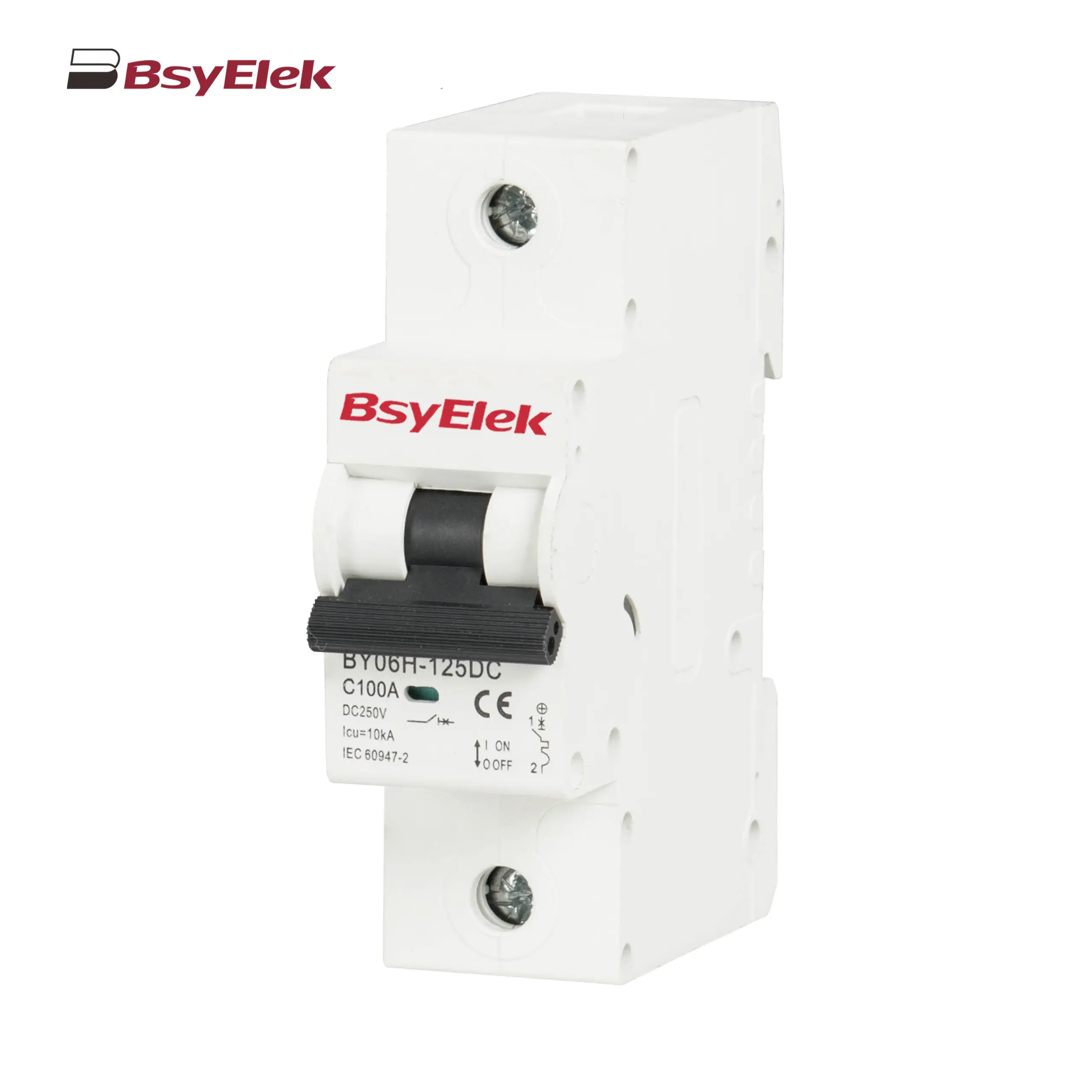 BY06H-125DC MCB 10-15kA DC Miniature Circuit Breaker
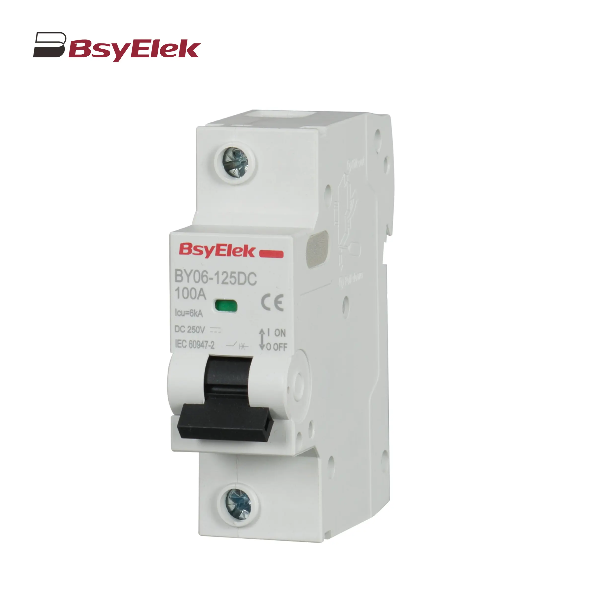 BY06-125DC MCB 6kA DC Miniature Circuit Breaker
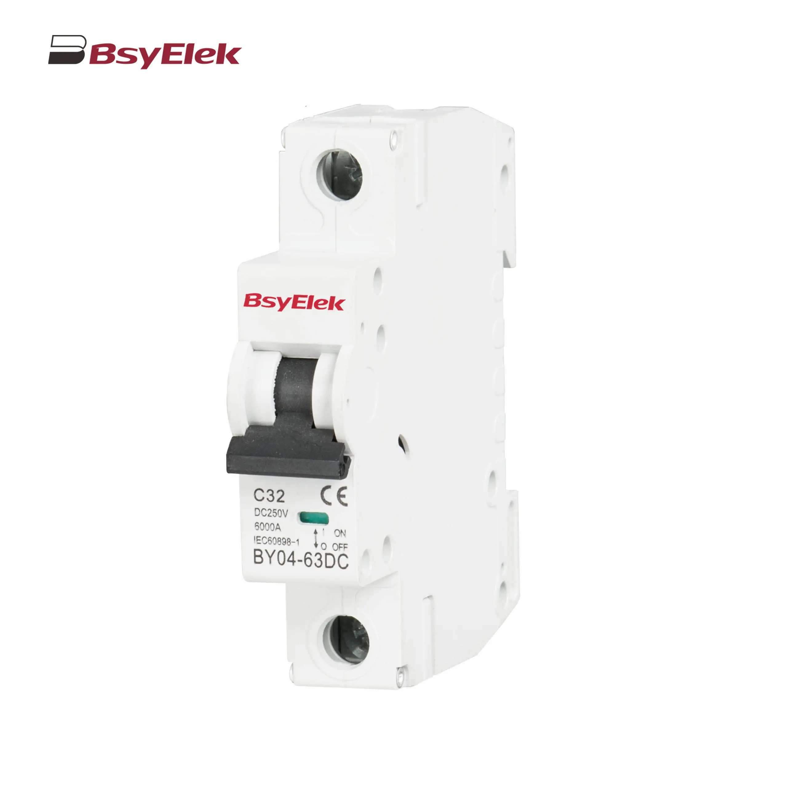 BY04-63DC MCB 6-10kA DC Miniature Circuit Breaker
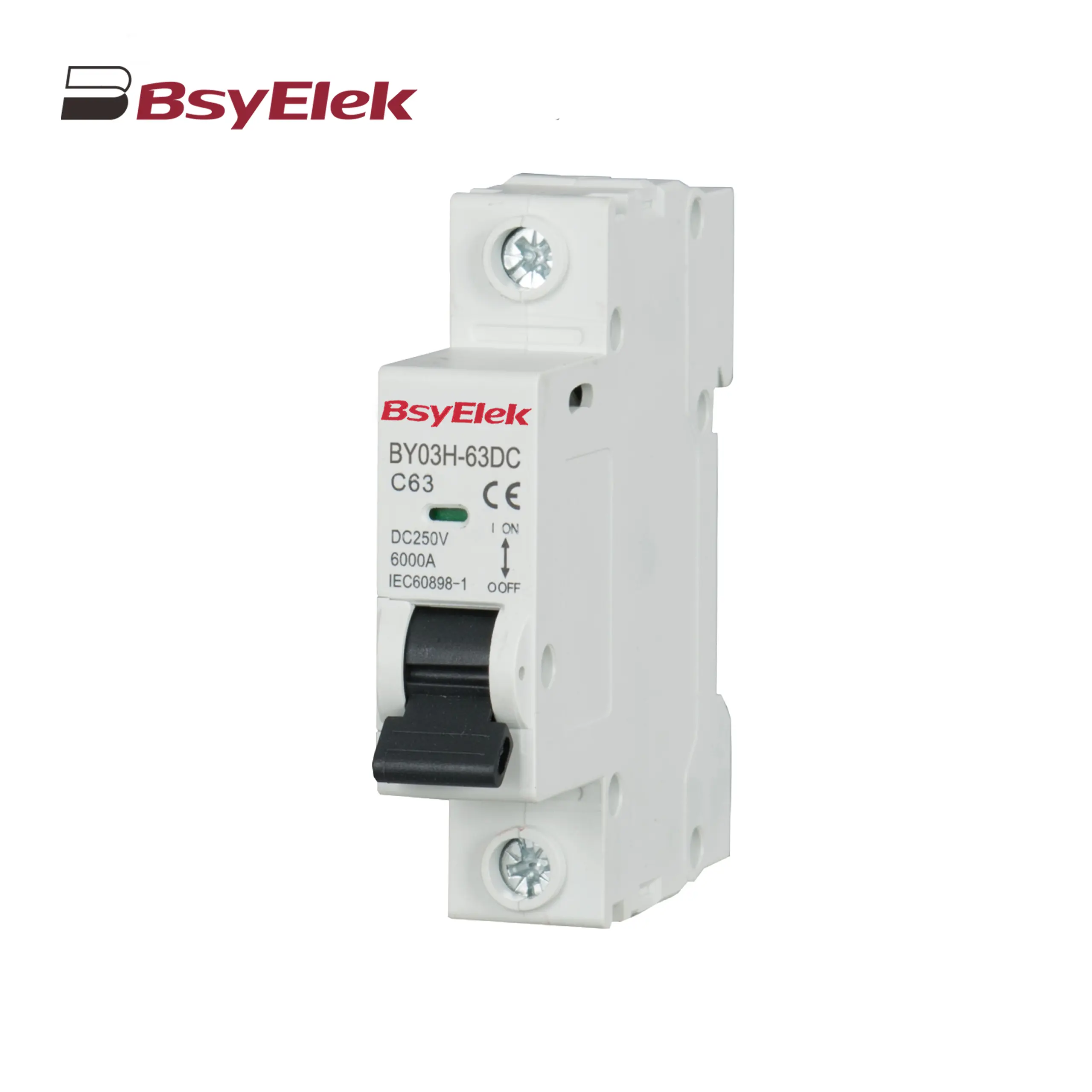 BY03H-63DC MCB 6kA DC Miniature Circuit Breaker
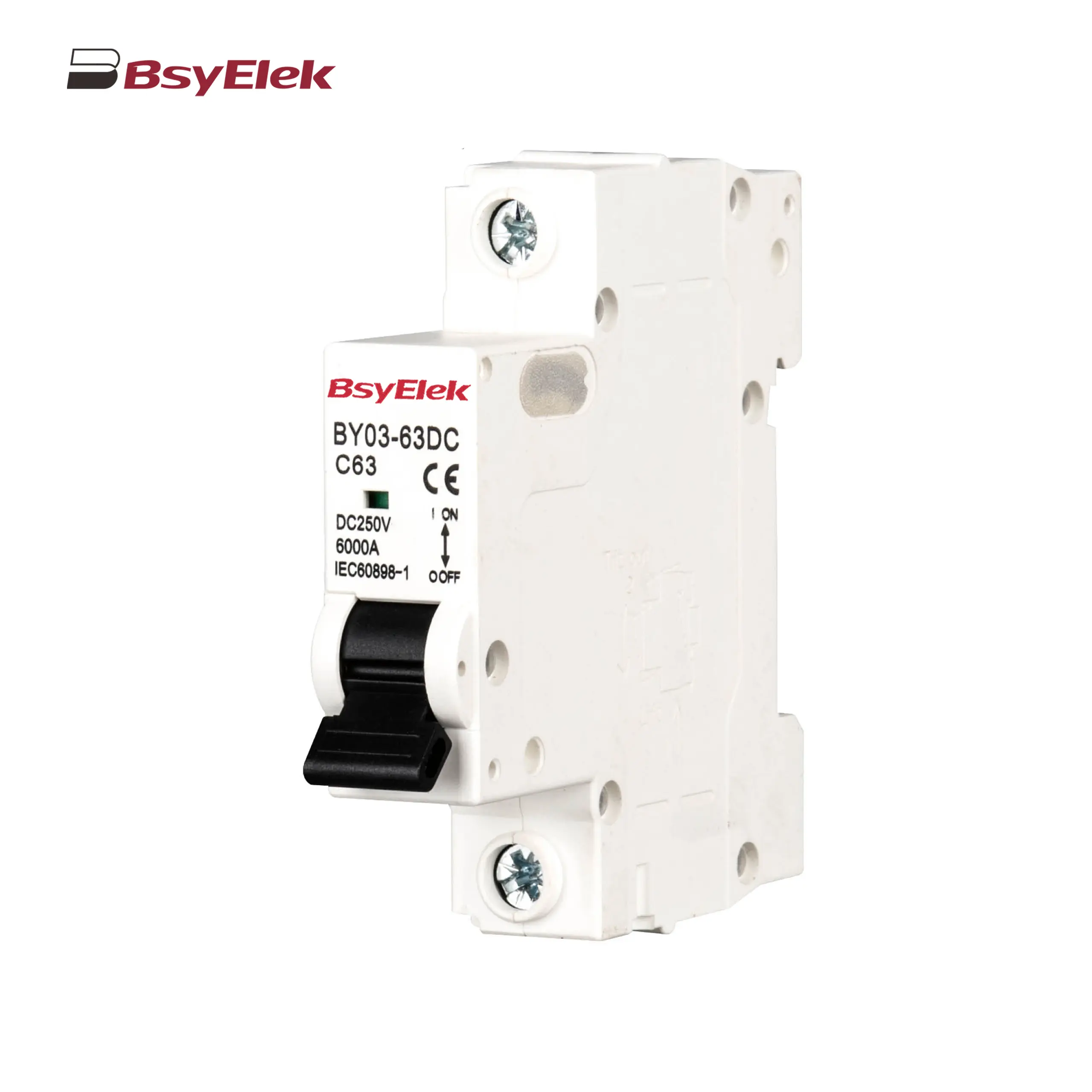 BY03-63DC MCB 4.5kA DC Miniature Circuit Breaker
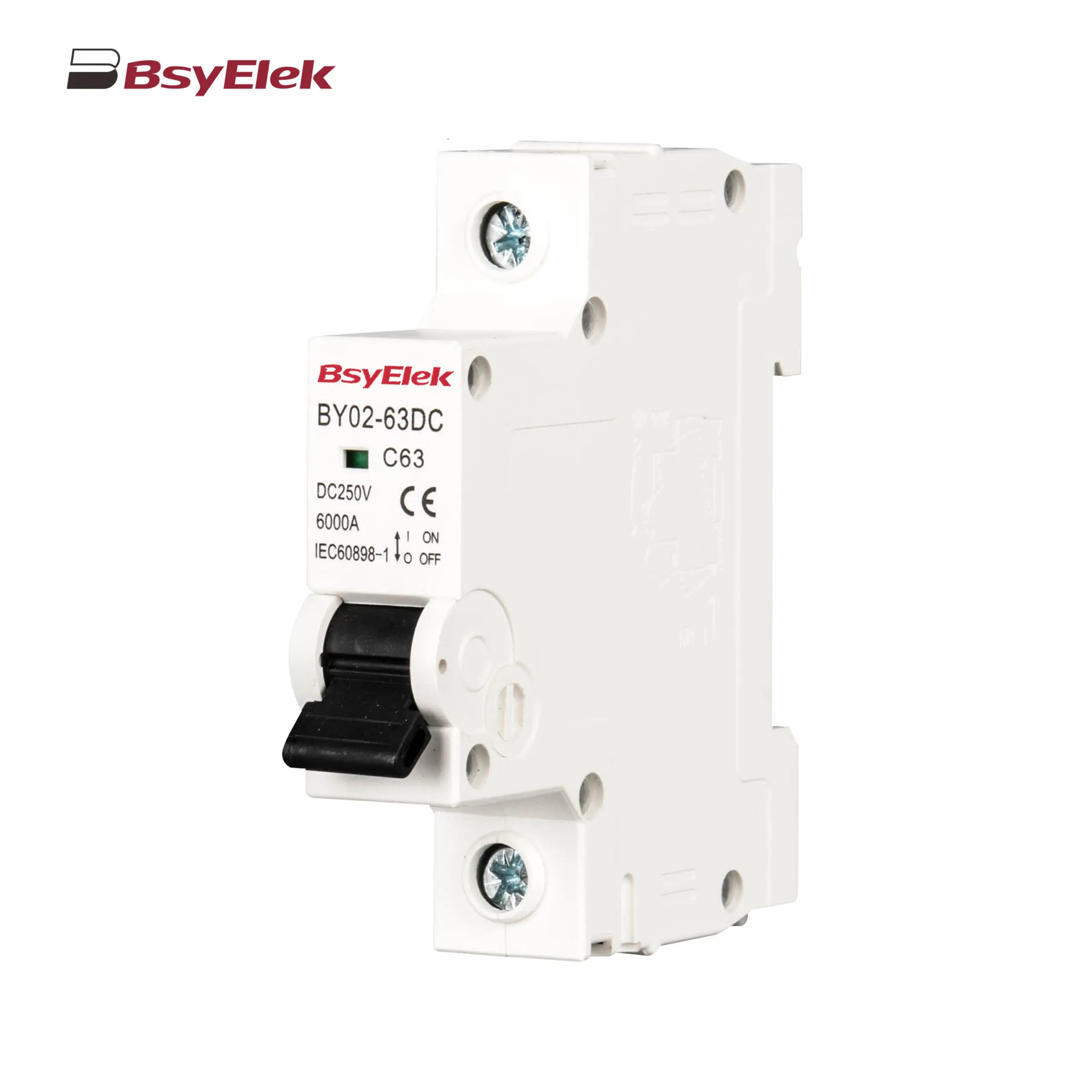 BY02-63DC MCB 3kA DC Miniature Circuit Breaker
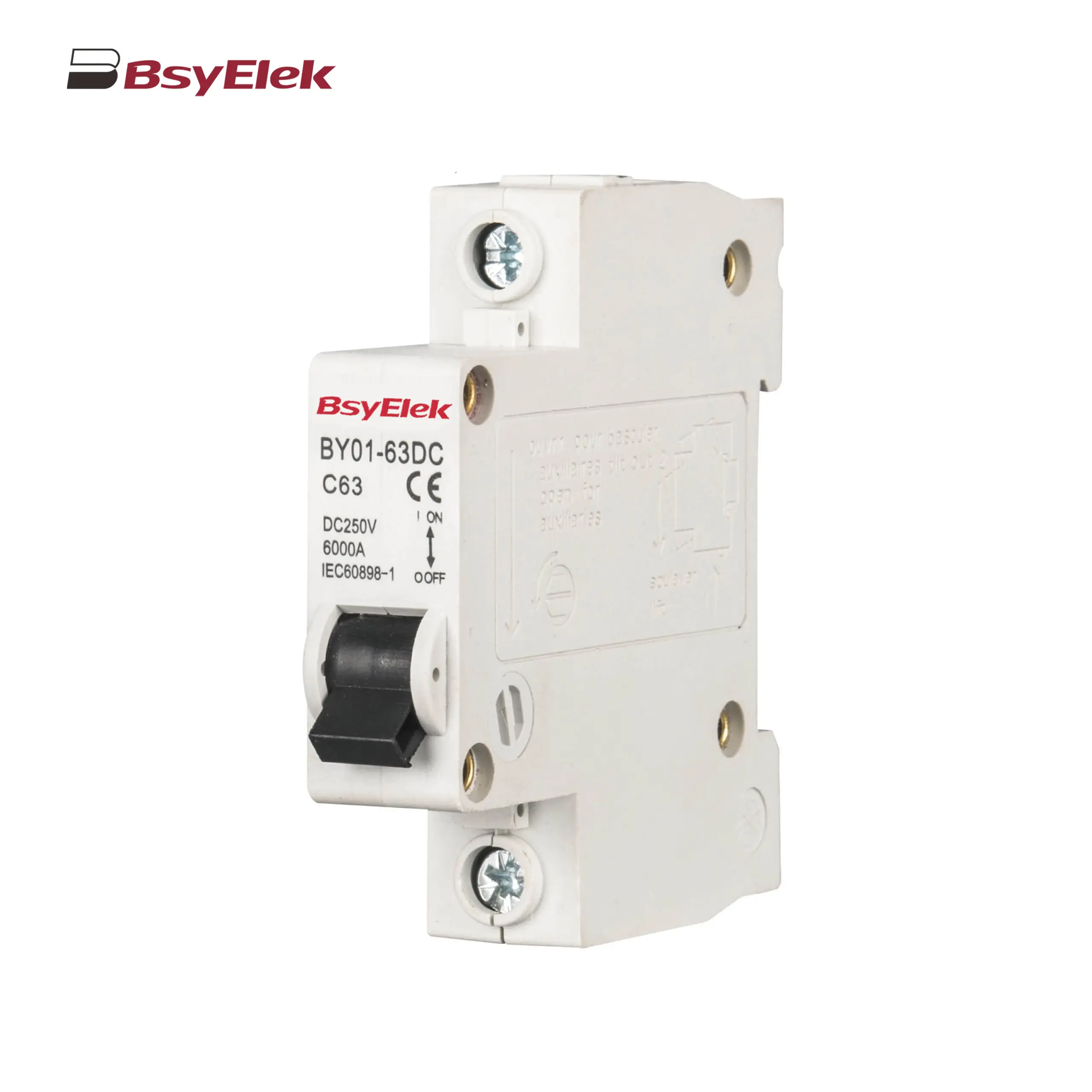 BY01-63DC MCB 3kA DC Miniature Circuit Breaker
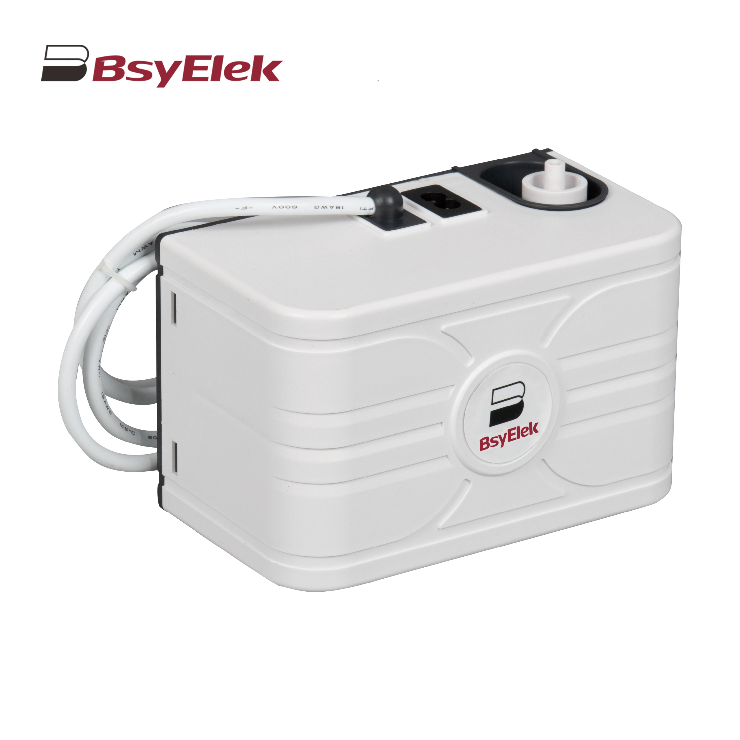 BY-5018 1.8M Engineering Drainage Pump
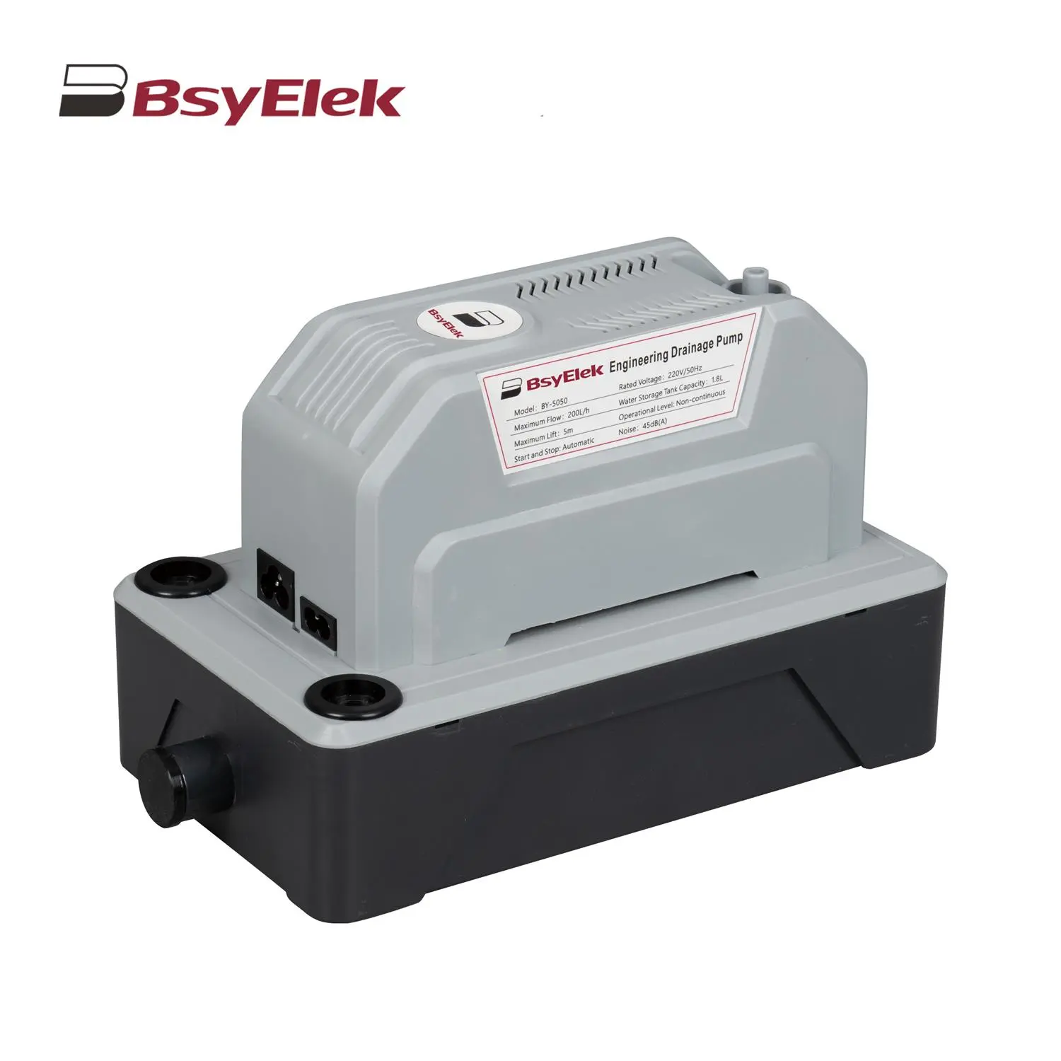 BY-5050 5M Engineering Drainage Pump
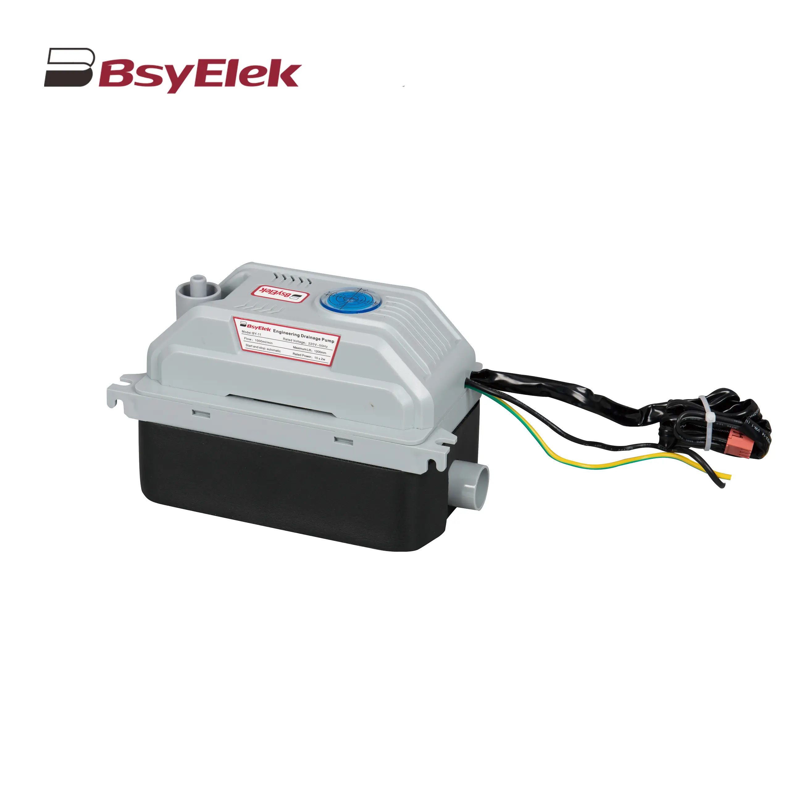 BY-11 1.2M Engineering Drainage Pump
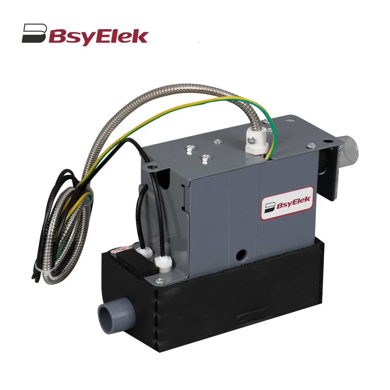 SBH-05 0.7M Original Drainage Pump of Duct Type Air Conditioner
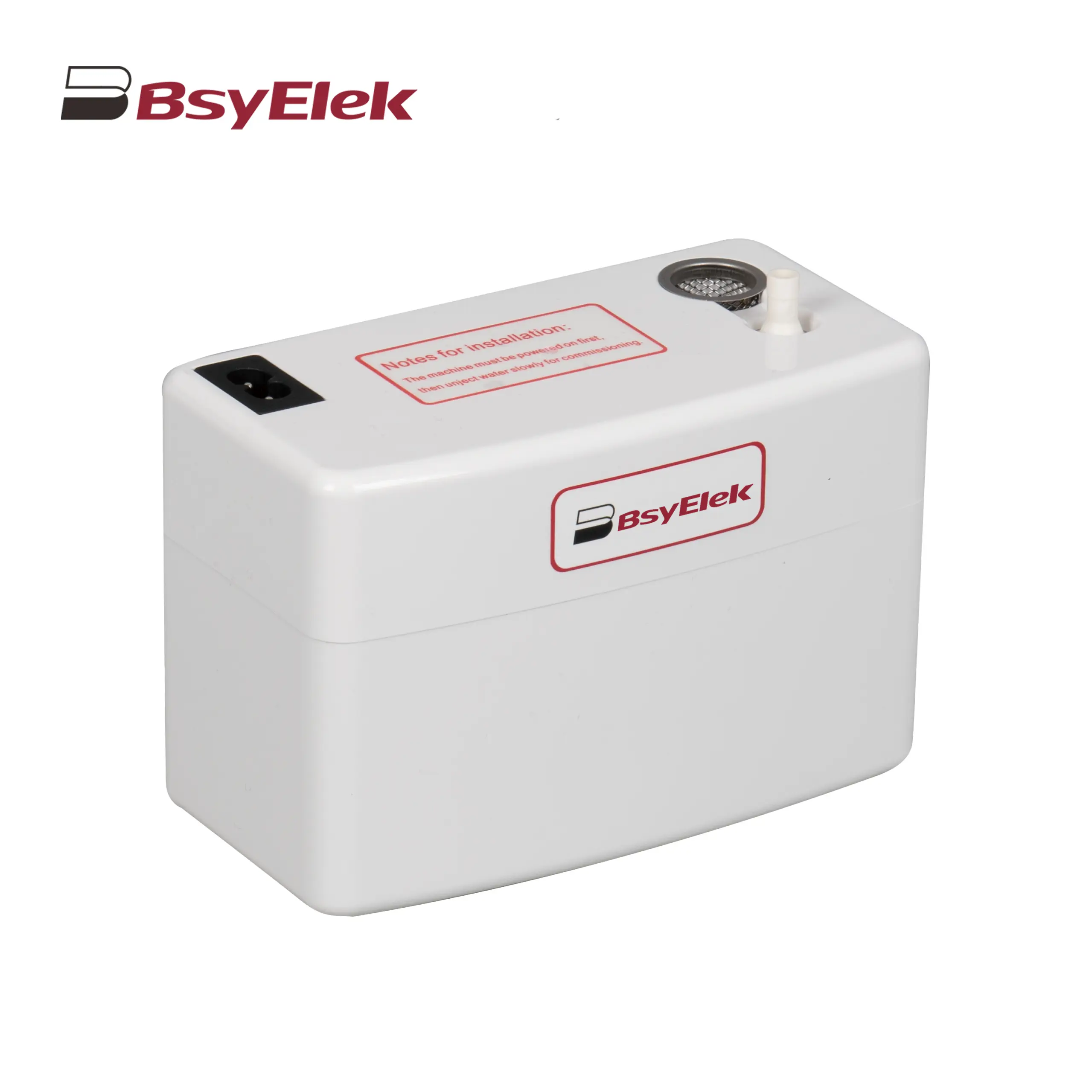 BY-24A/40A 10M Drainage Pump of Air Conditioner
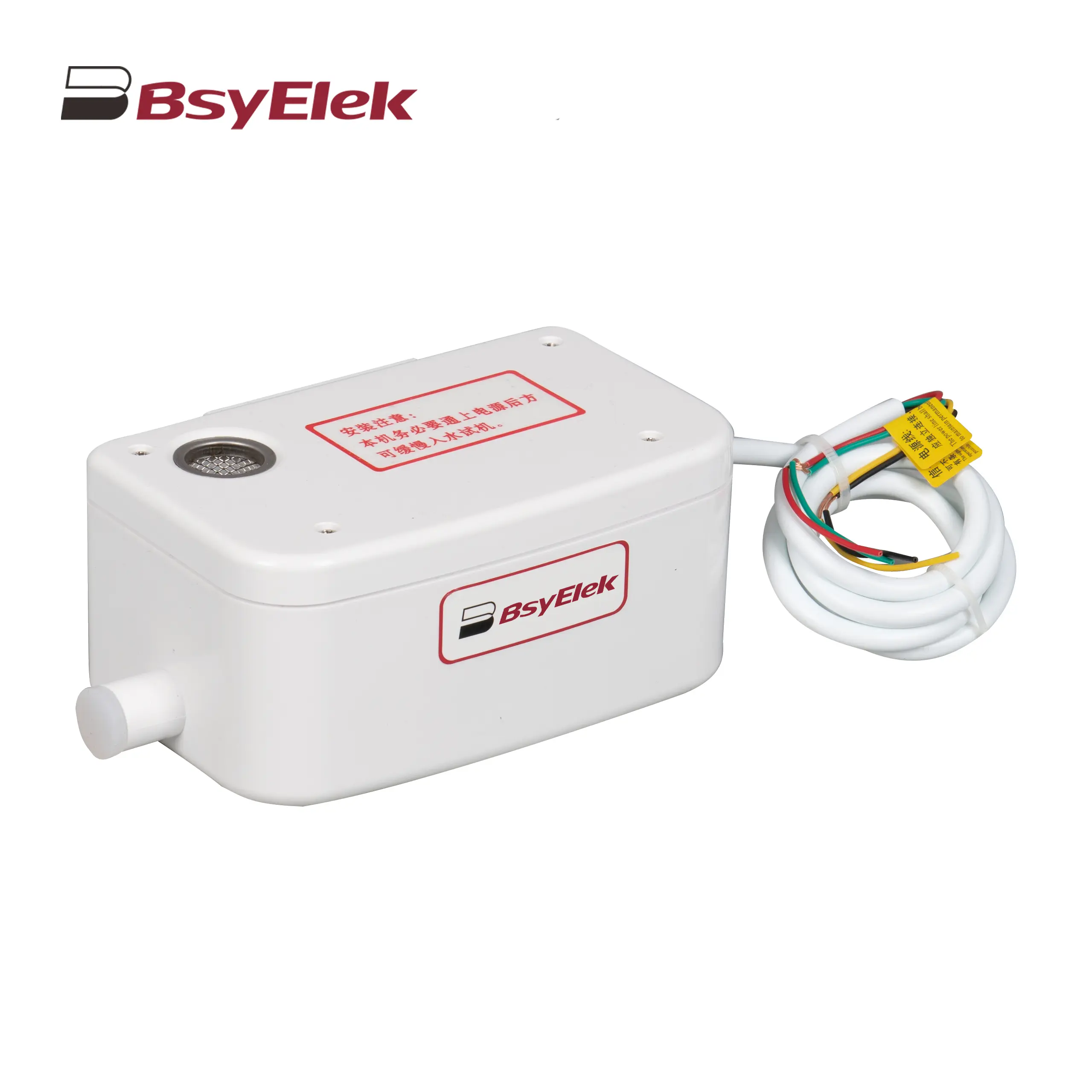 BY-50A 12M Drainage Pump of Air Conditioner
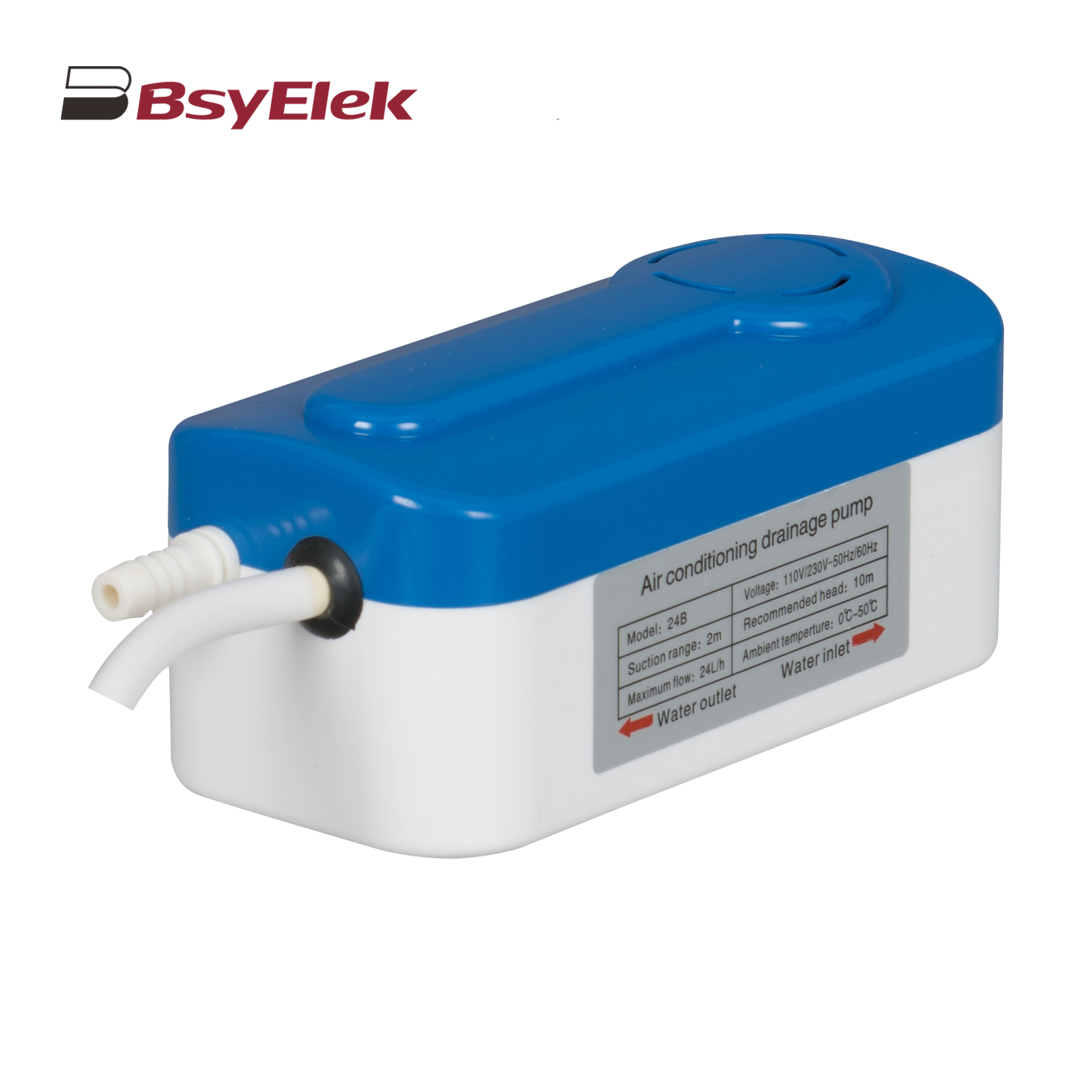 BY-24B/40B 10M Split Type Drainage Pump
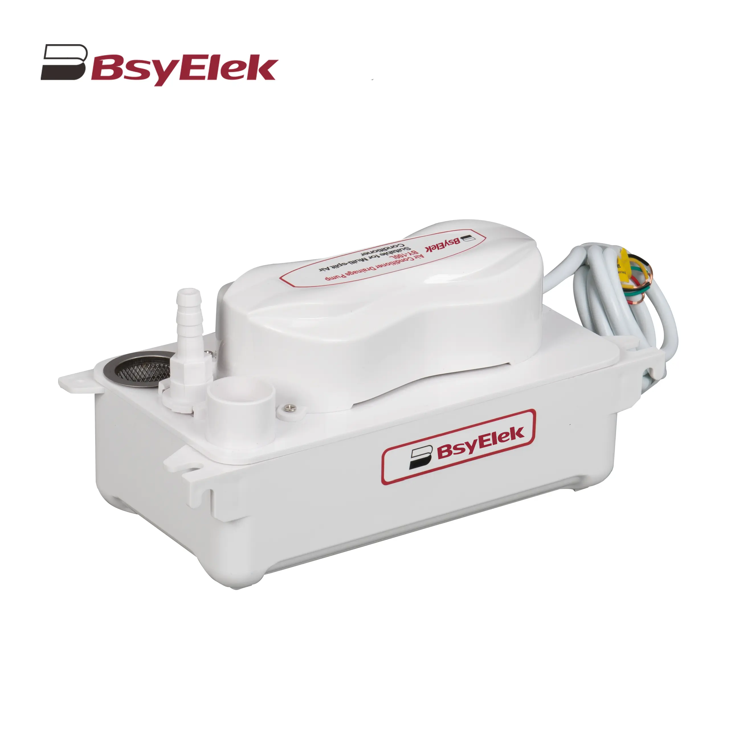 BY-100L 2M Drainage Pump of Air Conditioner
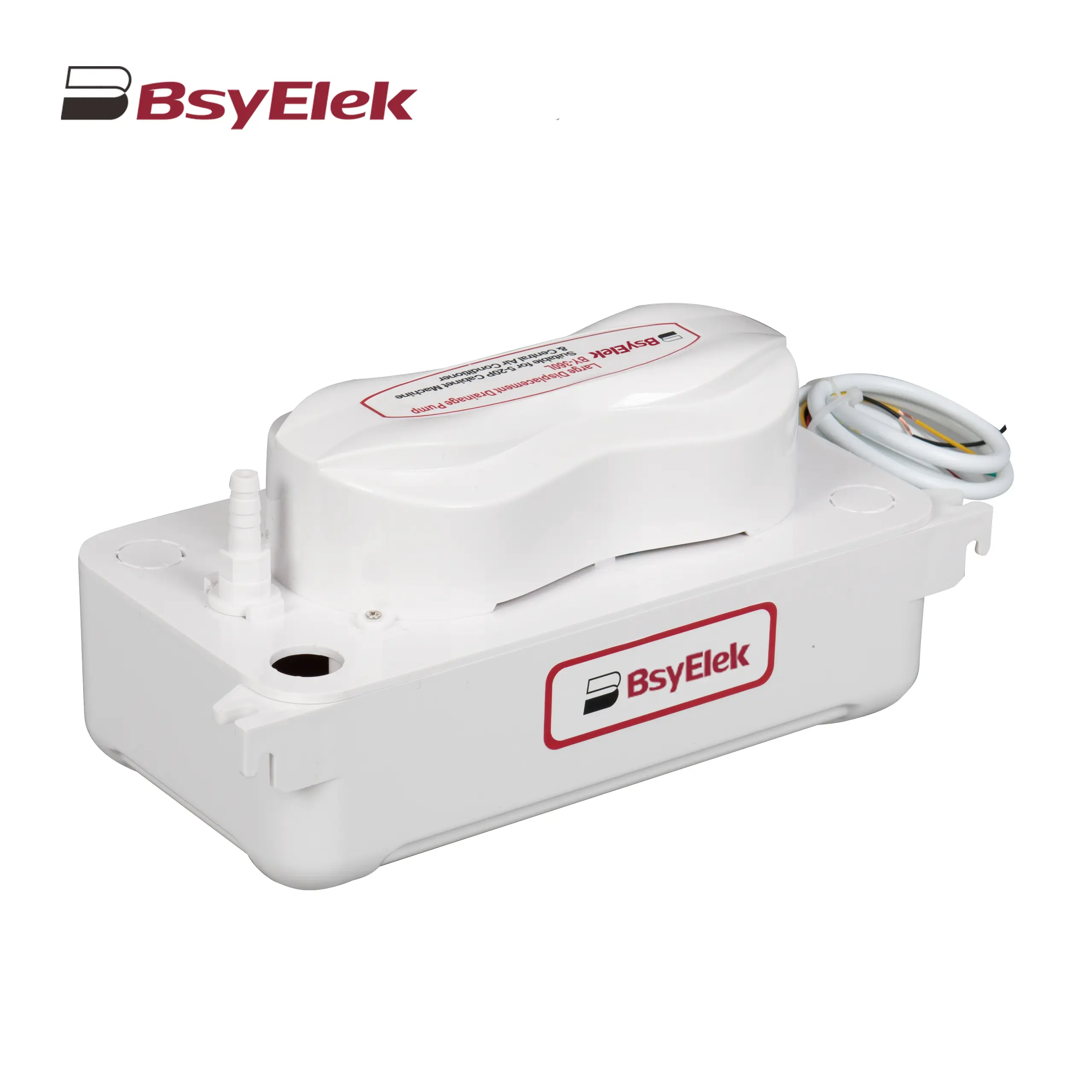 BY-360L 6M Large Displacement Drainage Pump
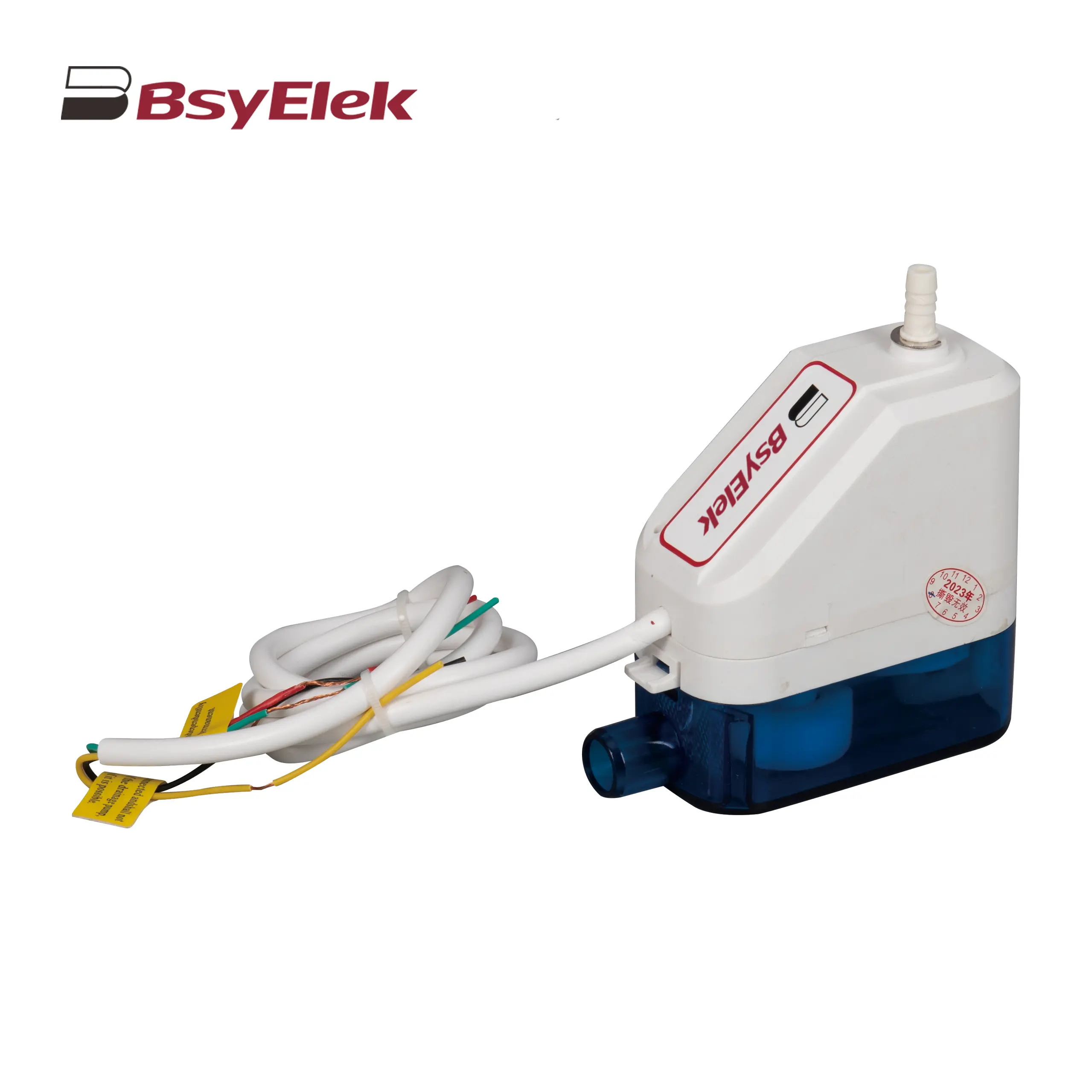 BY-24C/40C 10M Corner Drainage Pump
What is a miniature circuit breaker (MCB)?
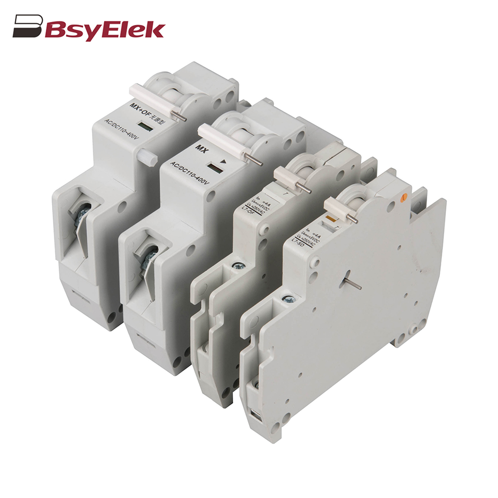 OF SD MX OF MCB Miniature Circuit Breaker Accessories
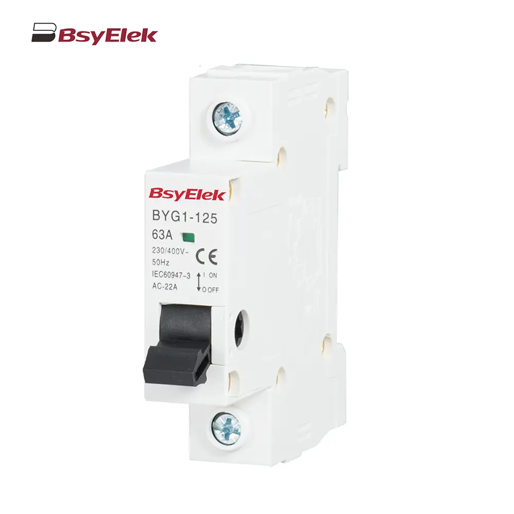 BYG1-125 Main Switch MCB Isolator Switch
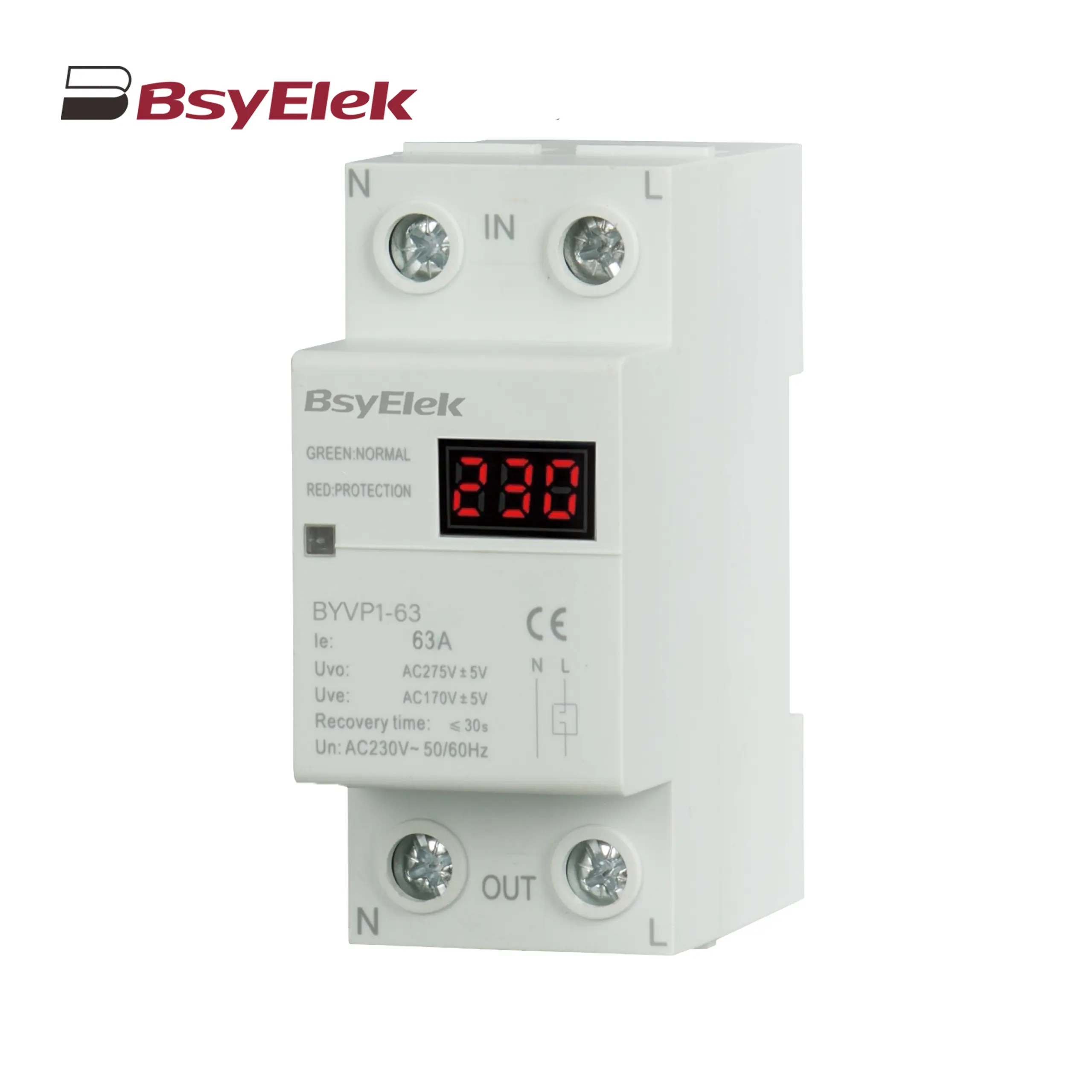 BYVP1-63 100A Single Display Overvoltage and Undervoltage Protector
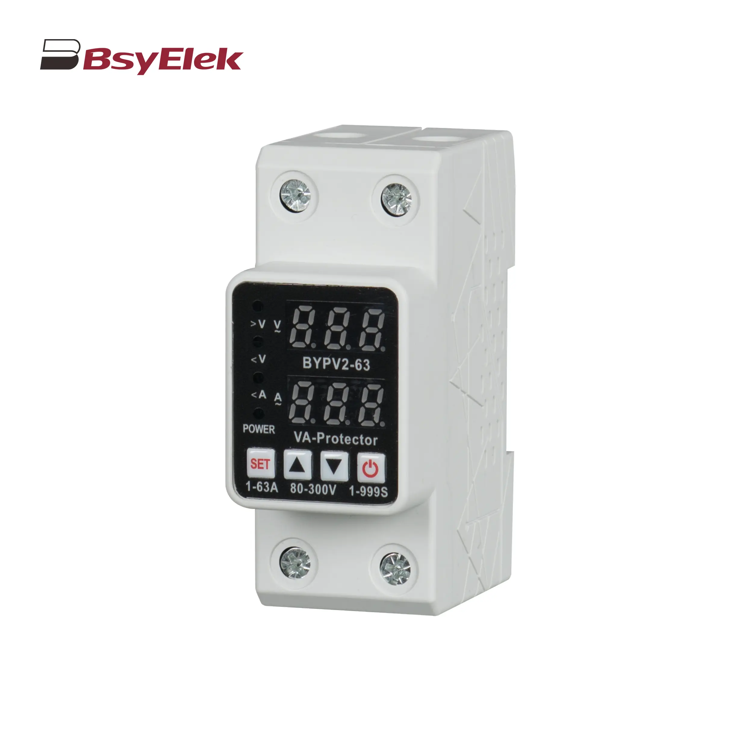 BYVP2-63 40A 63A Adjustable Dual Display Overvoltage and Undervoltage Protector
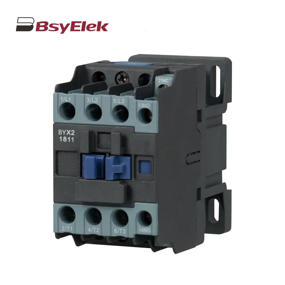 BYX2 6-95A AC Contactor
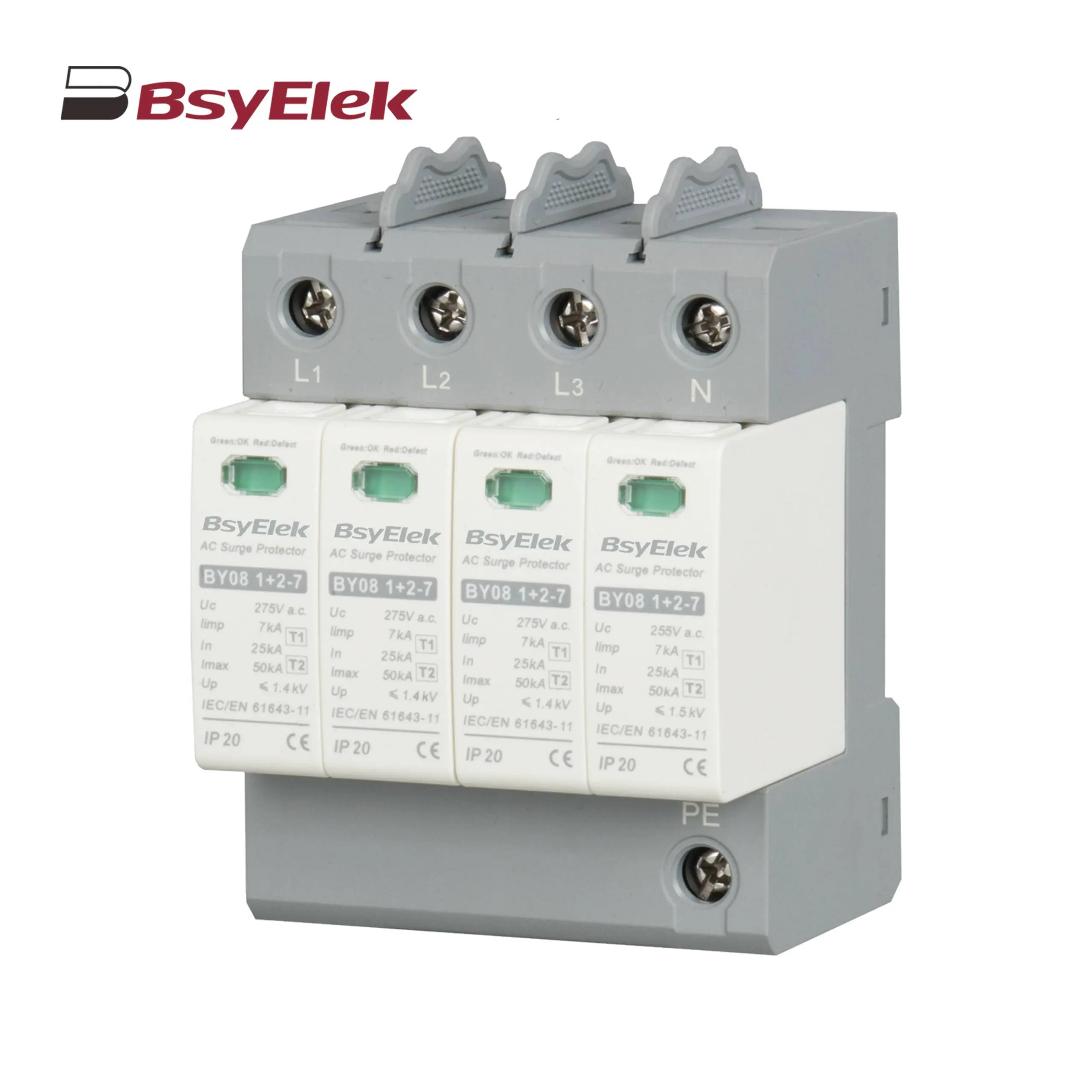 BY08 1+2-7 SPD Class T1+T2 Imax 50KA Surge Protective Device
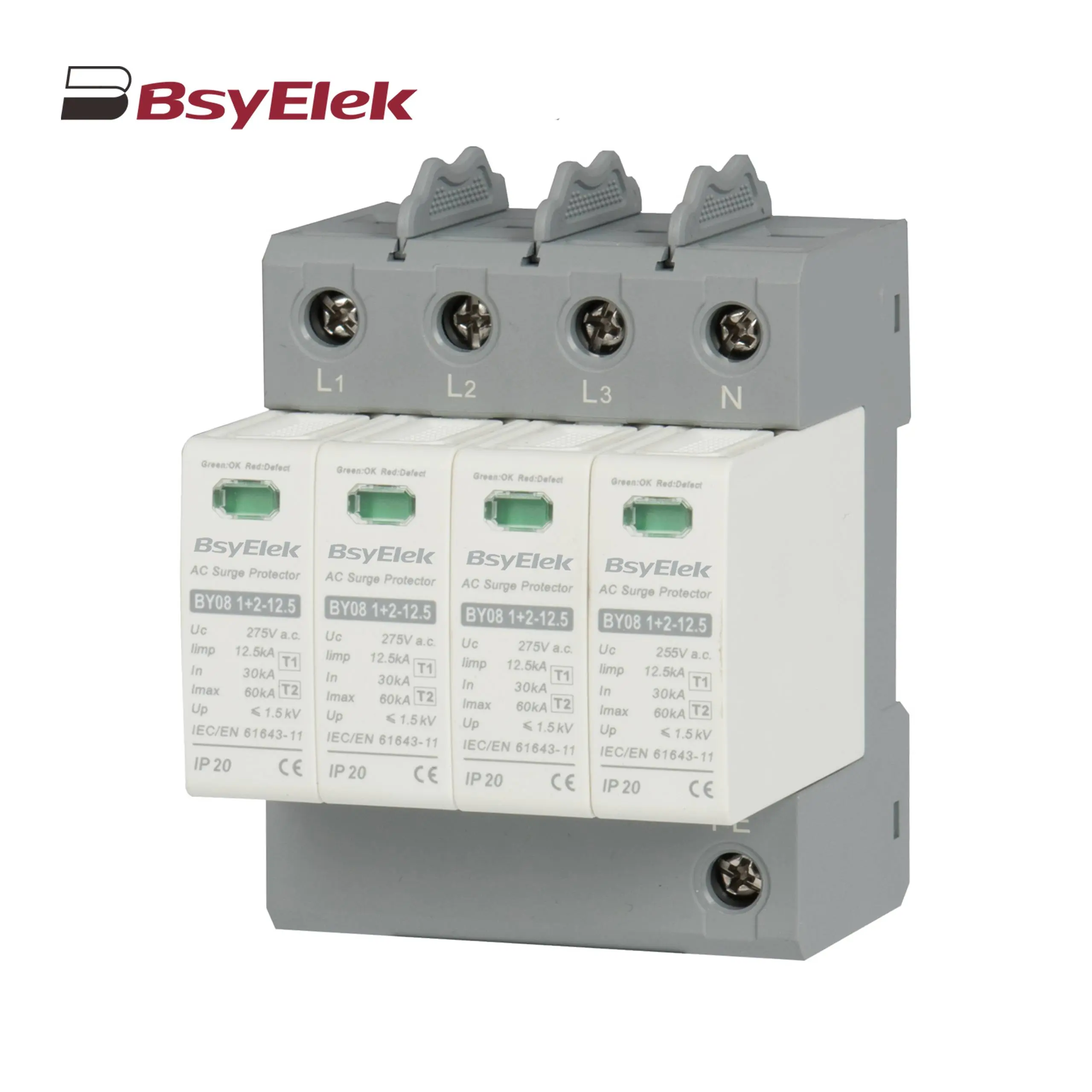 BY08 1+2-12.5 SPD Class T1+T2 Imax 60KA Surge Protective Device
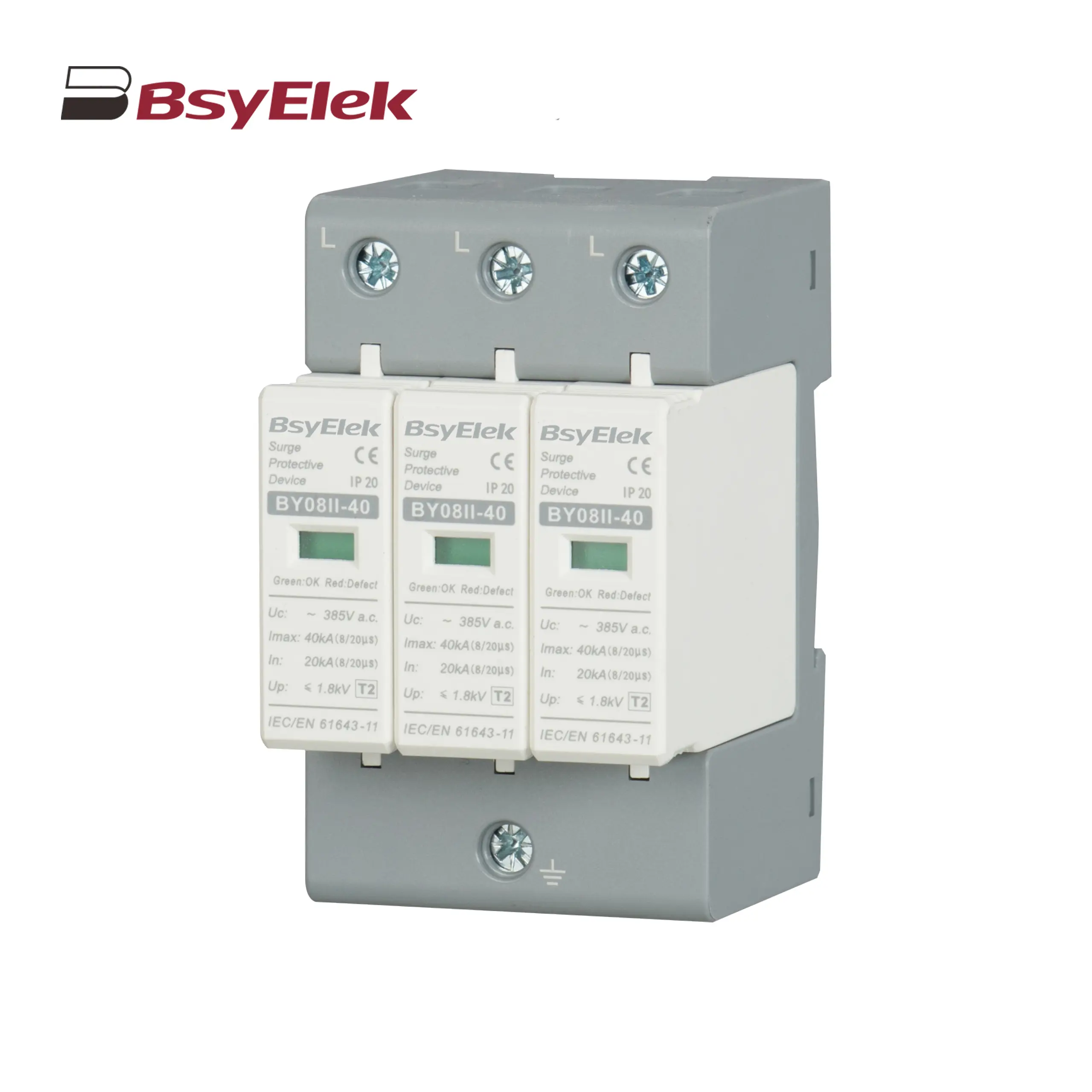 BY08II-40 SPD Class T2 Imax 40KA Surge Protective Device
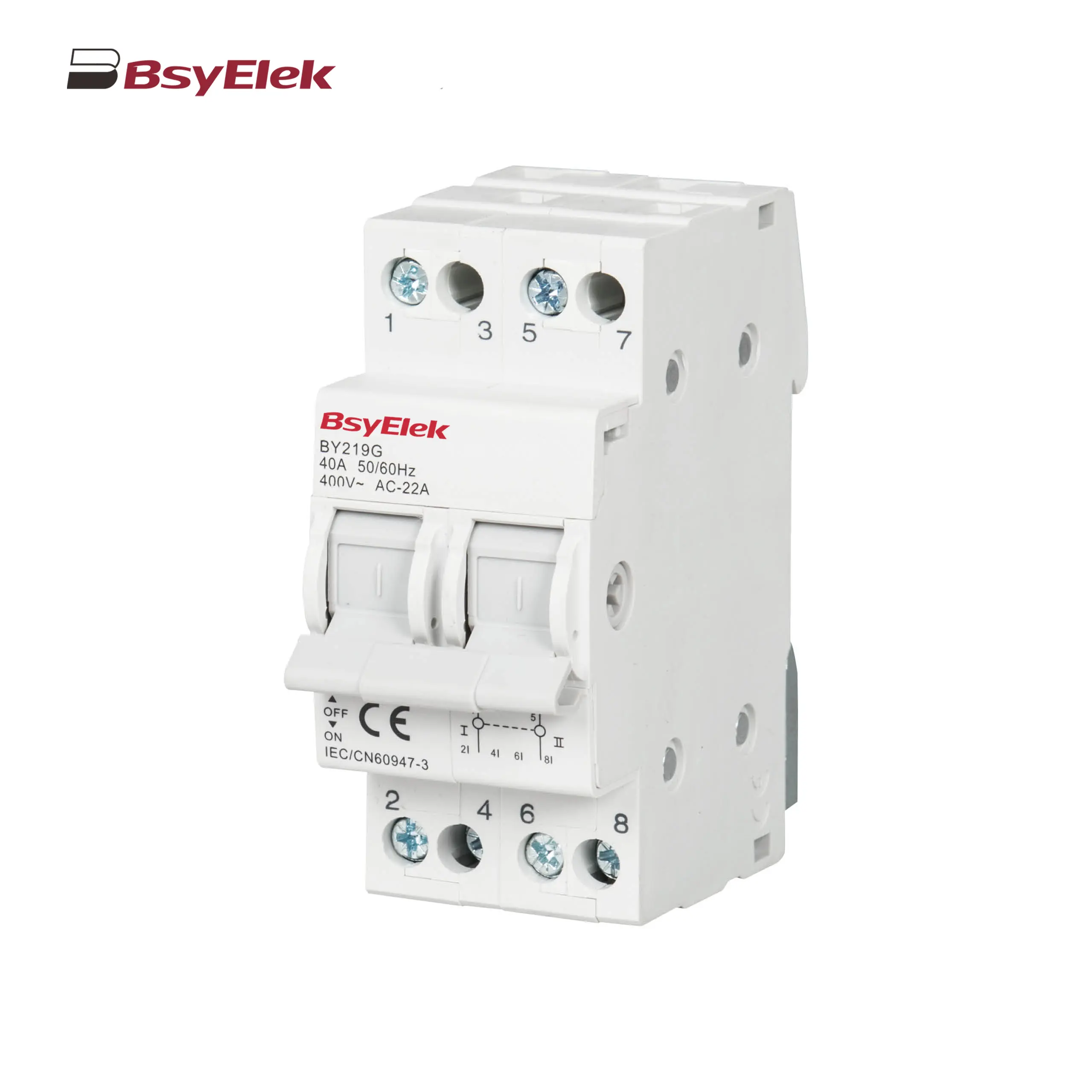 BY19G 63A Manual Changeover Switch
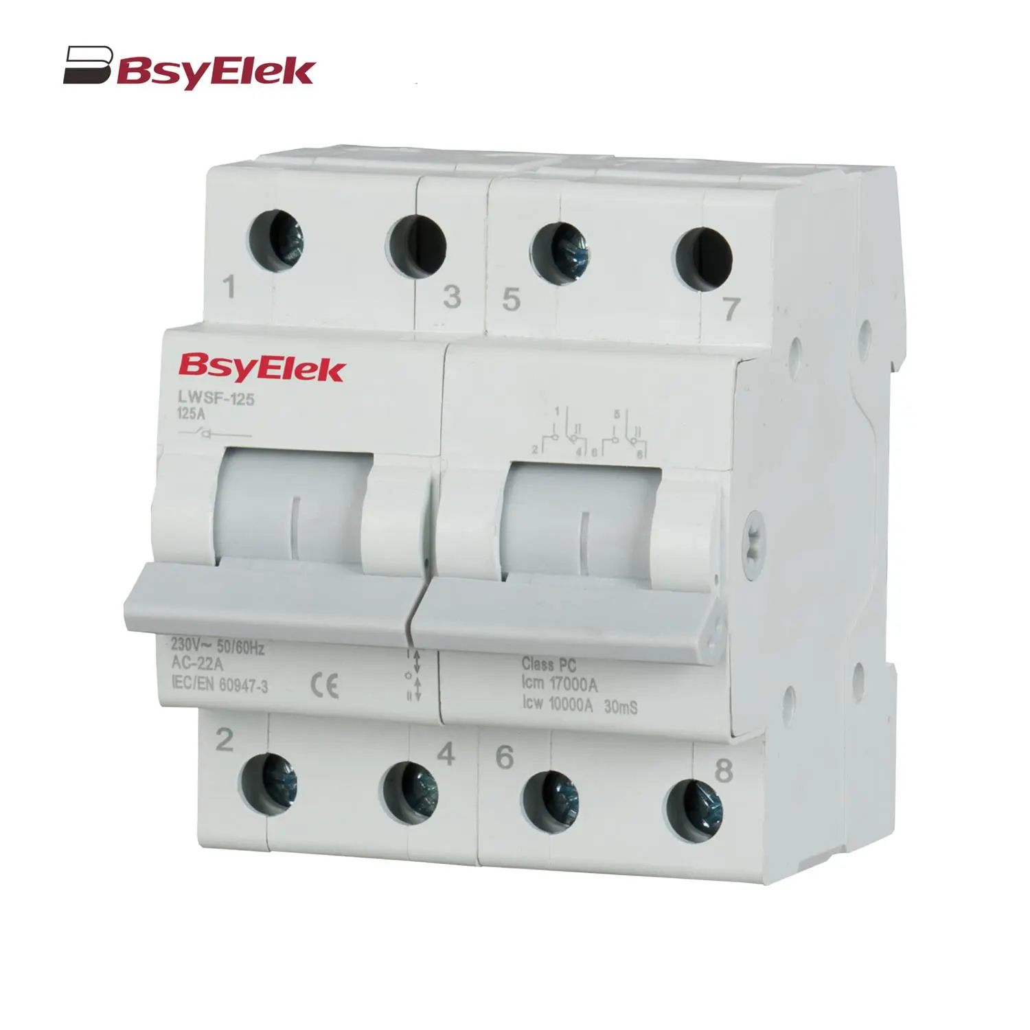 LWSF-125 125A Manual Changeover Switch
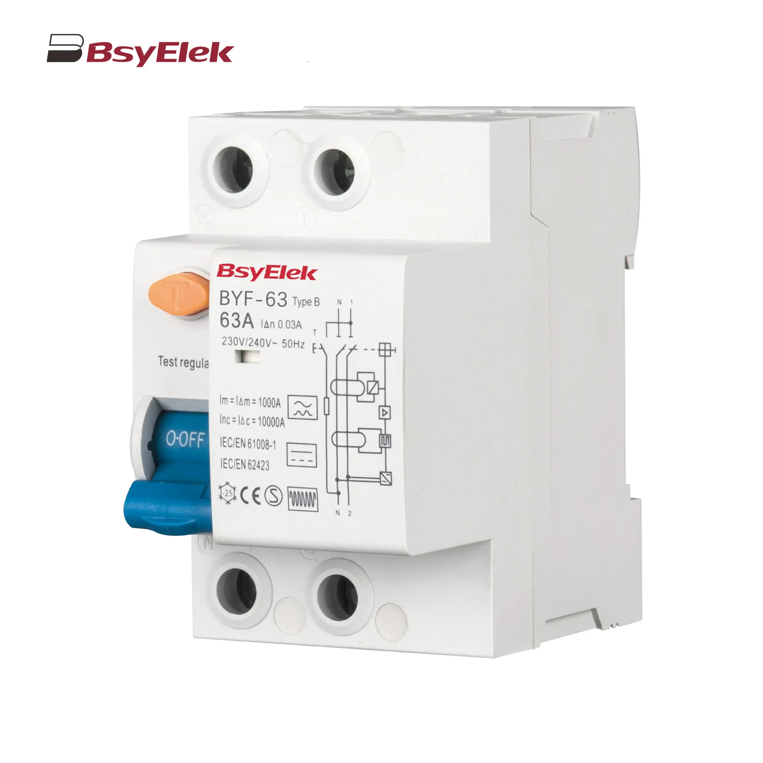 BYF-63 RCD 10KA Type B AC+A+Smoothing DC Residual Current Device
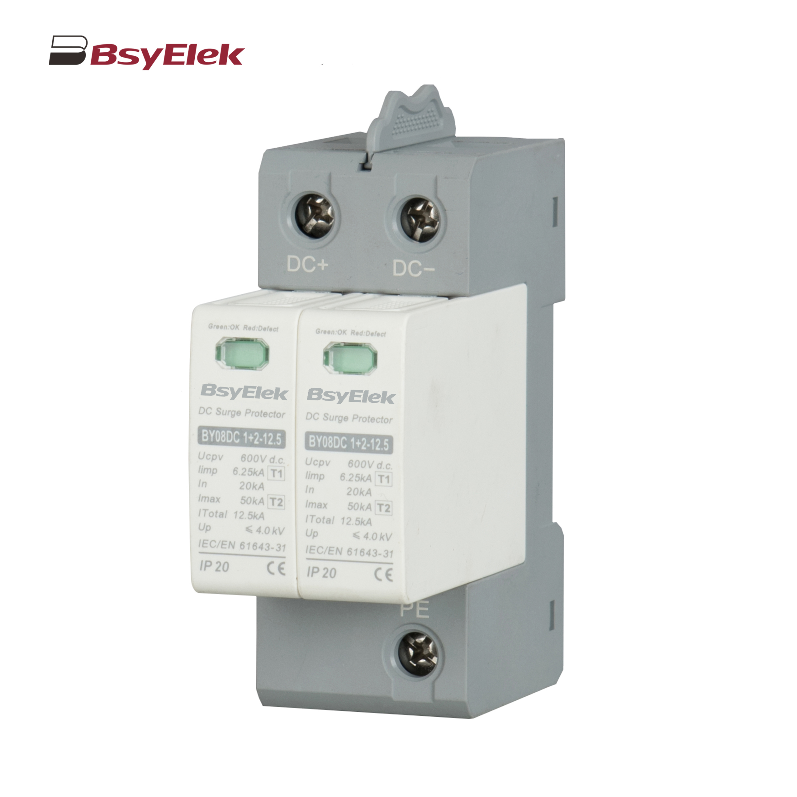 BY08DC 1+2-12.5 SPD Class T1+T2 40KA DC Surge Protective Device
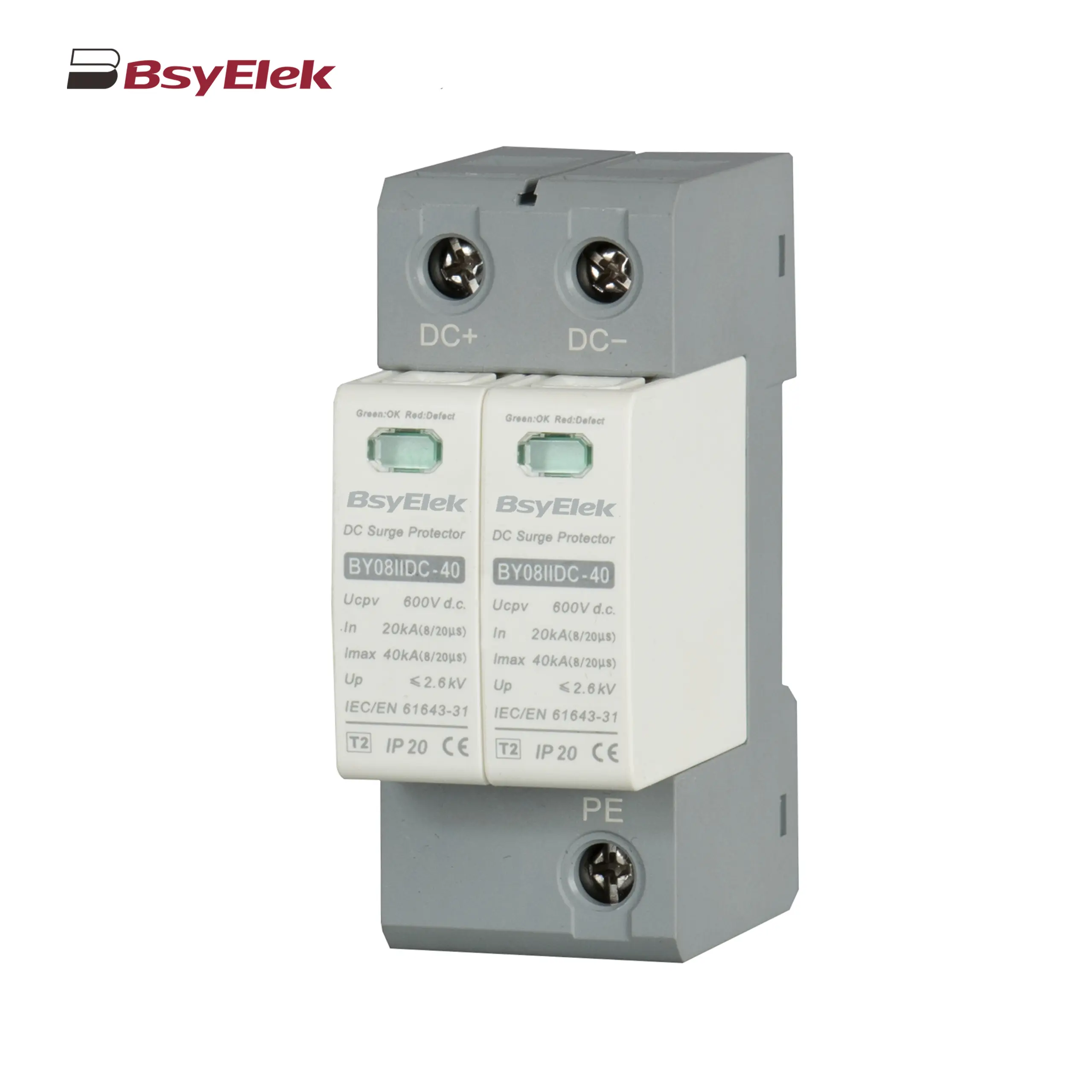 BY08IIDC-40 SPD Class T2 40KA DC Surge Protective Device
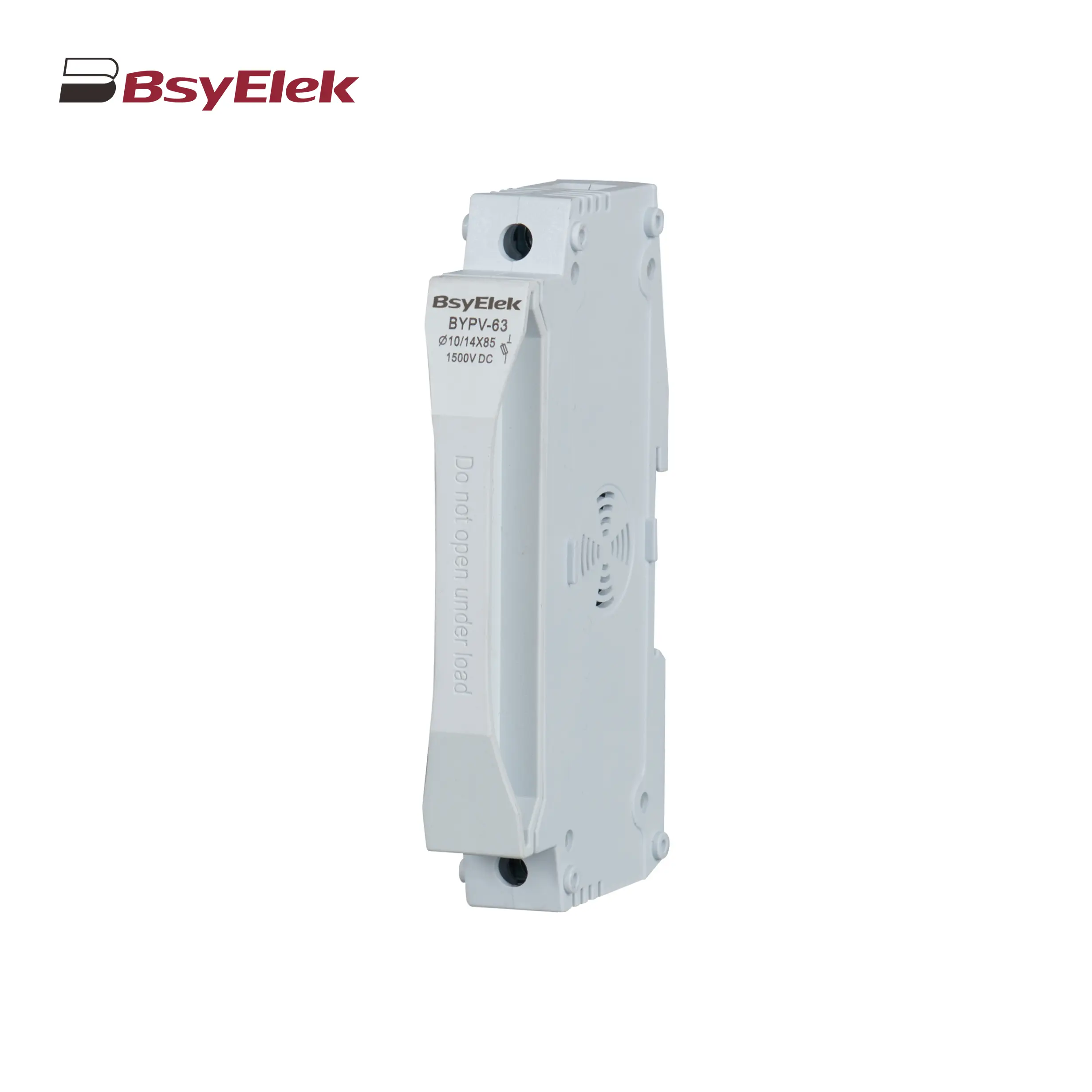 BYPV-63 1500VDC 50A Fuse Holder with 10x85mm 14x85mm Fuse Link
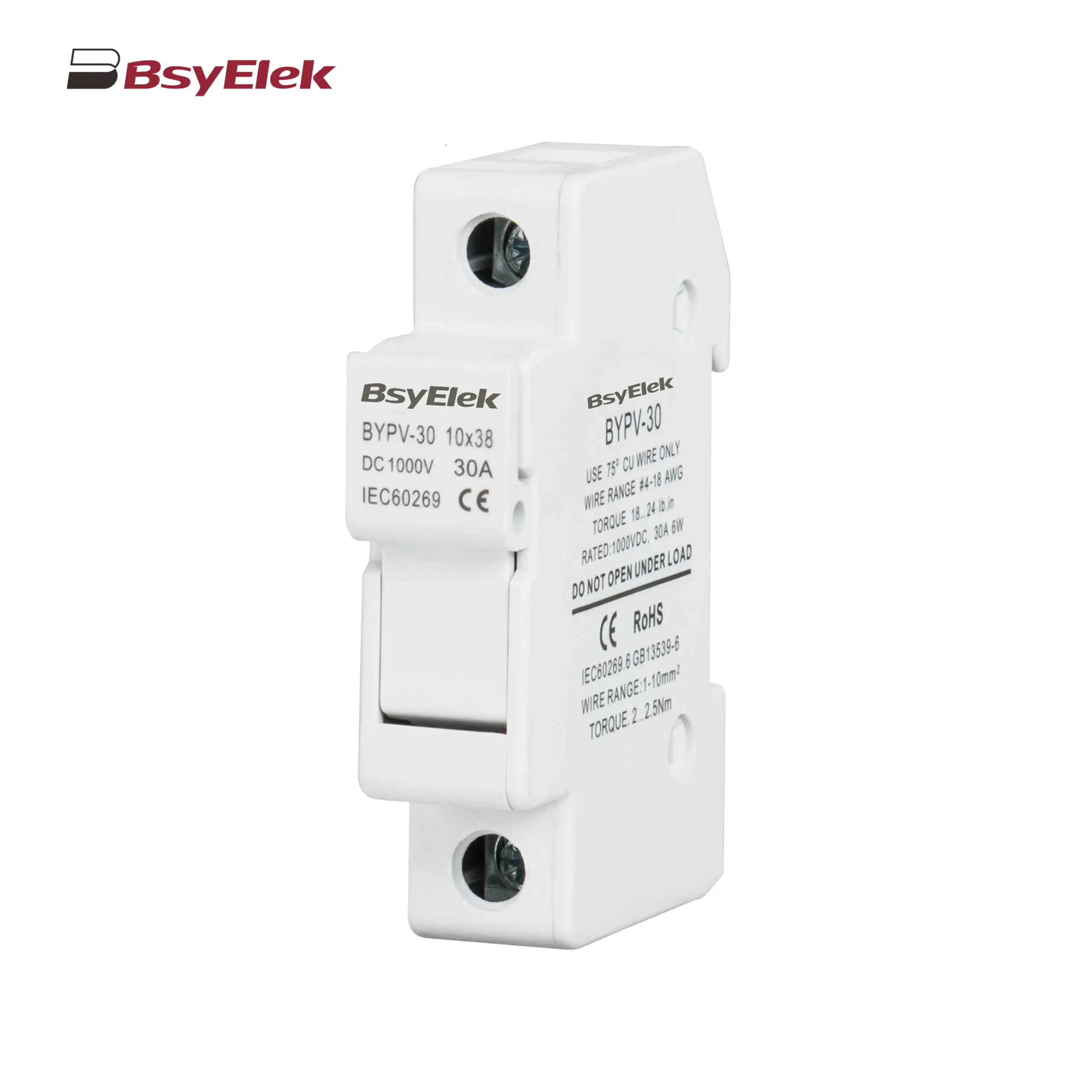 BYPV-30 1000VDC 32A Fuse Holder with 10x38mm Fuse Link
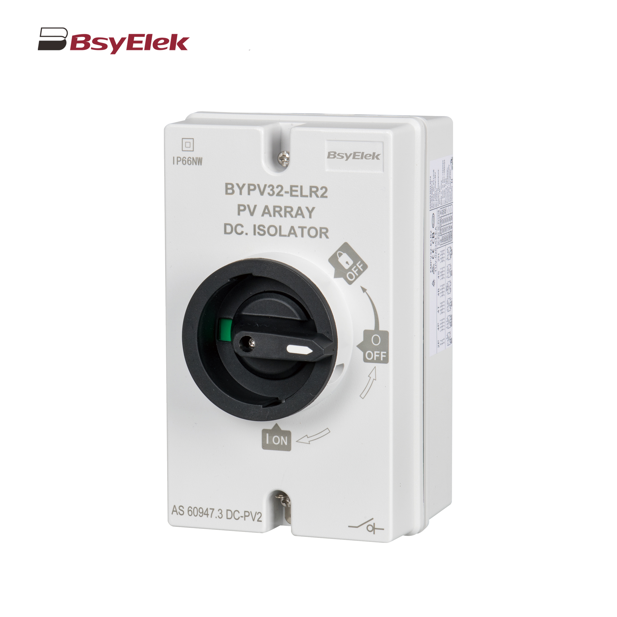 BYPV-ELR2 PV Isolator Switch with Enclosed Version
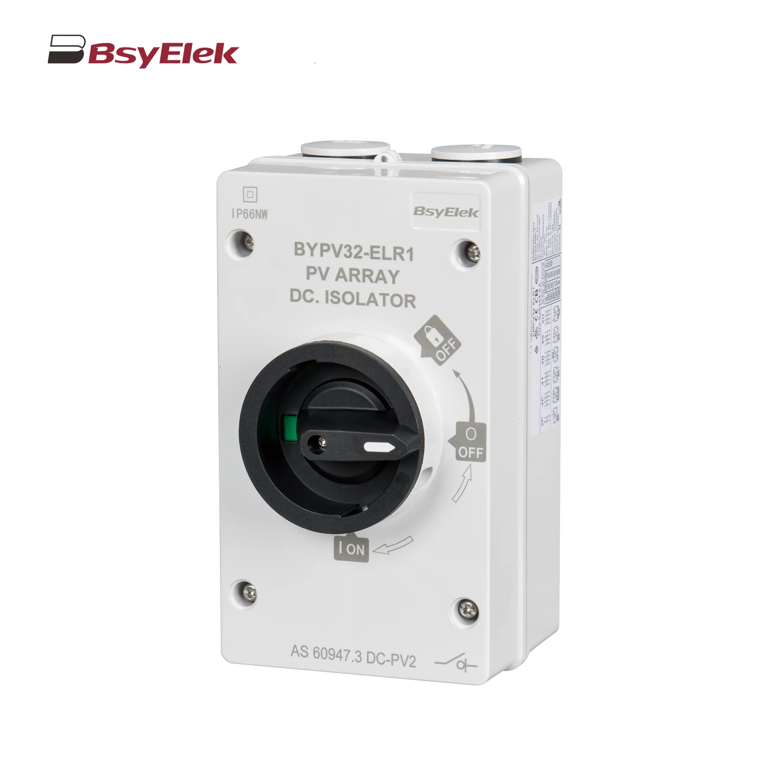 BYPV-ELR1 PV Isolator Switch with Enclosed Version
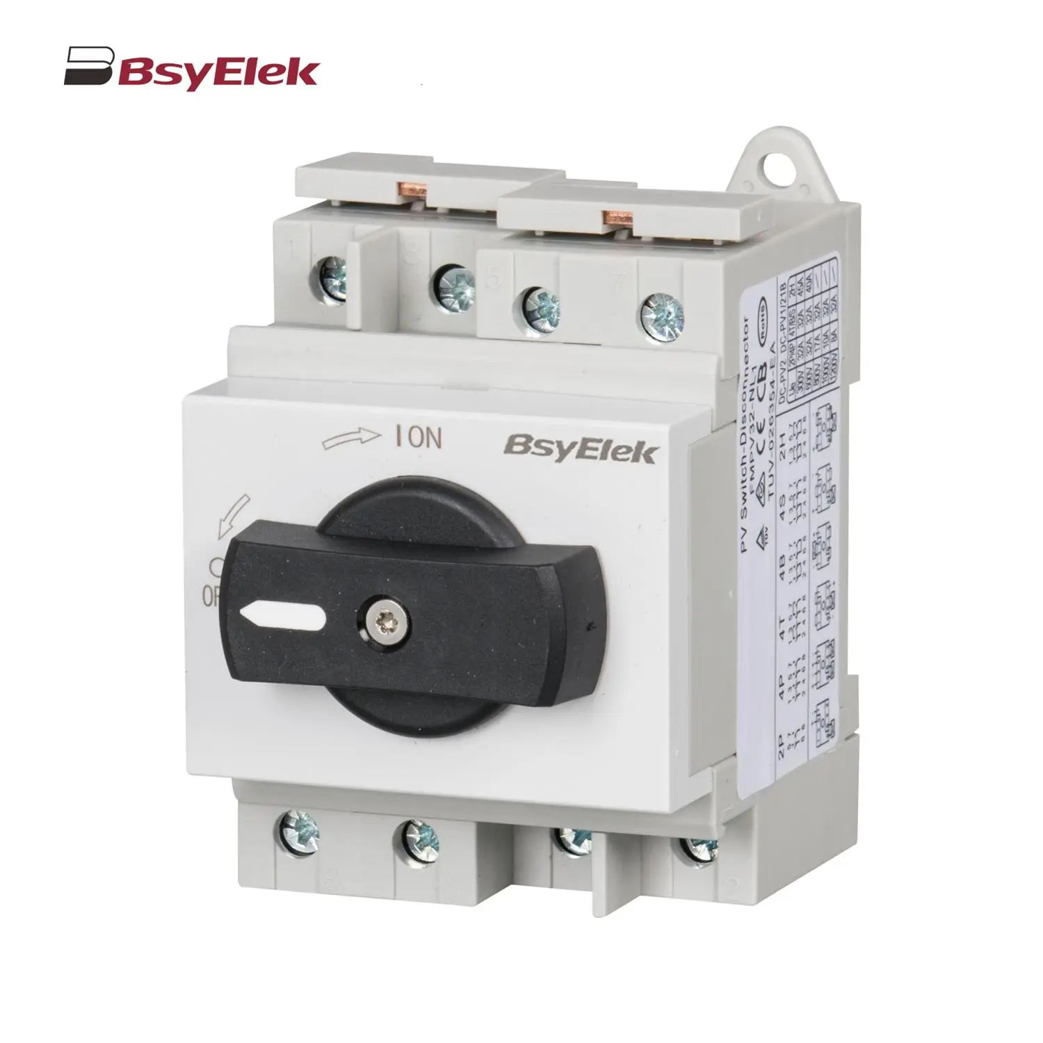 BYPV-NL1/T PV Isolator Switch with Ultra-thin Lever Handle
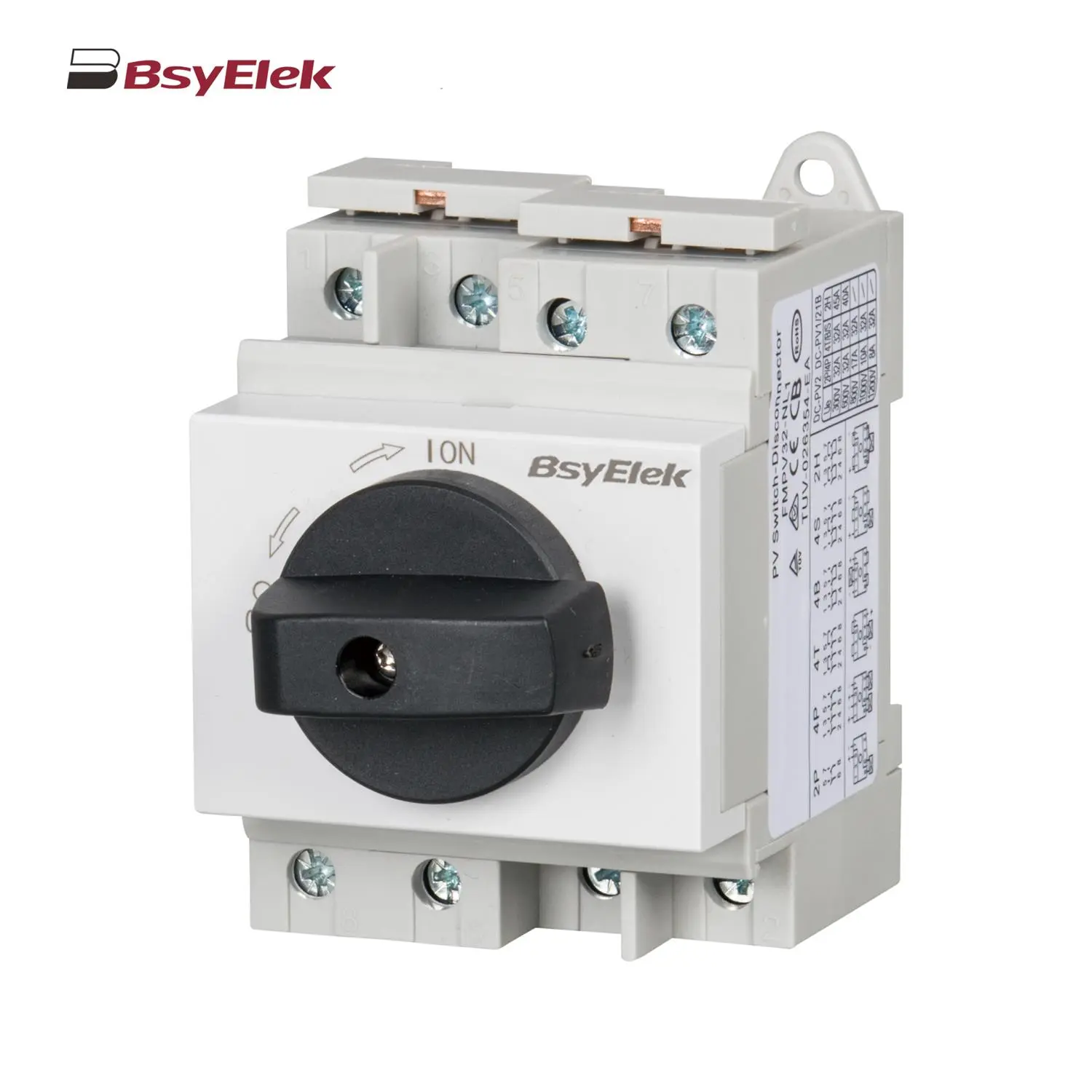 BYPV-NL1 PV Isolator Switch with Lever Handle
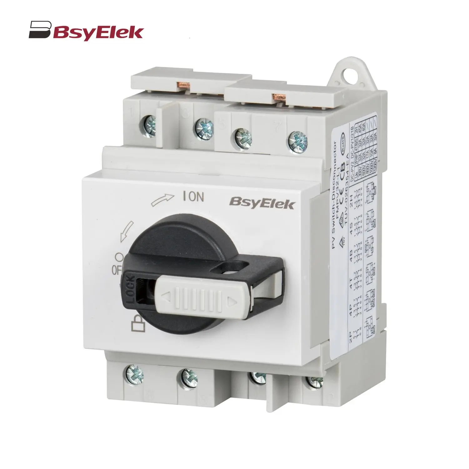 BYPV-L1/L2 PV Isolator Switch with Lockable Lever Handle
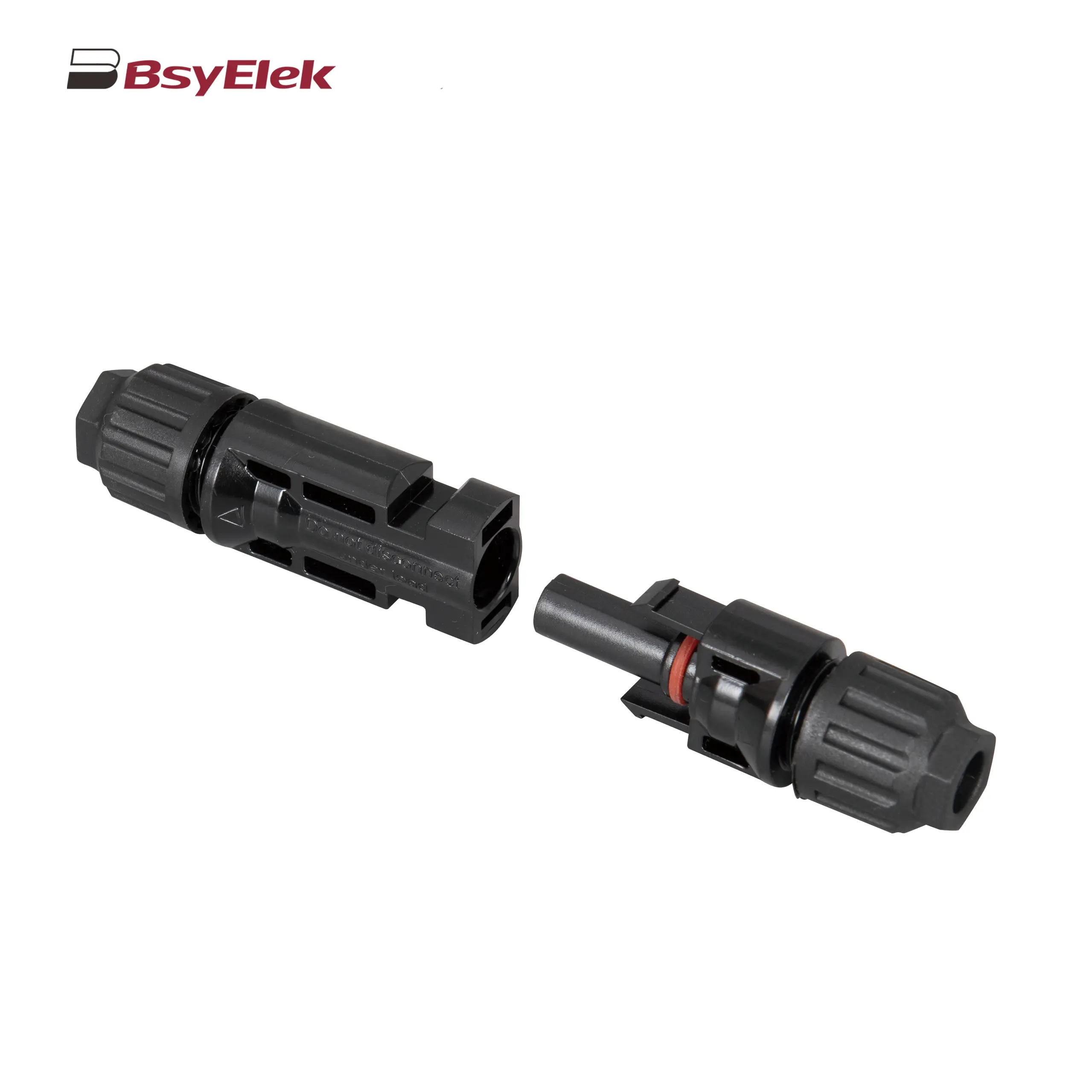 PV-BY-01 30A/50A 1000V Photovoltaic Connector
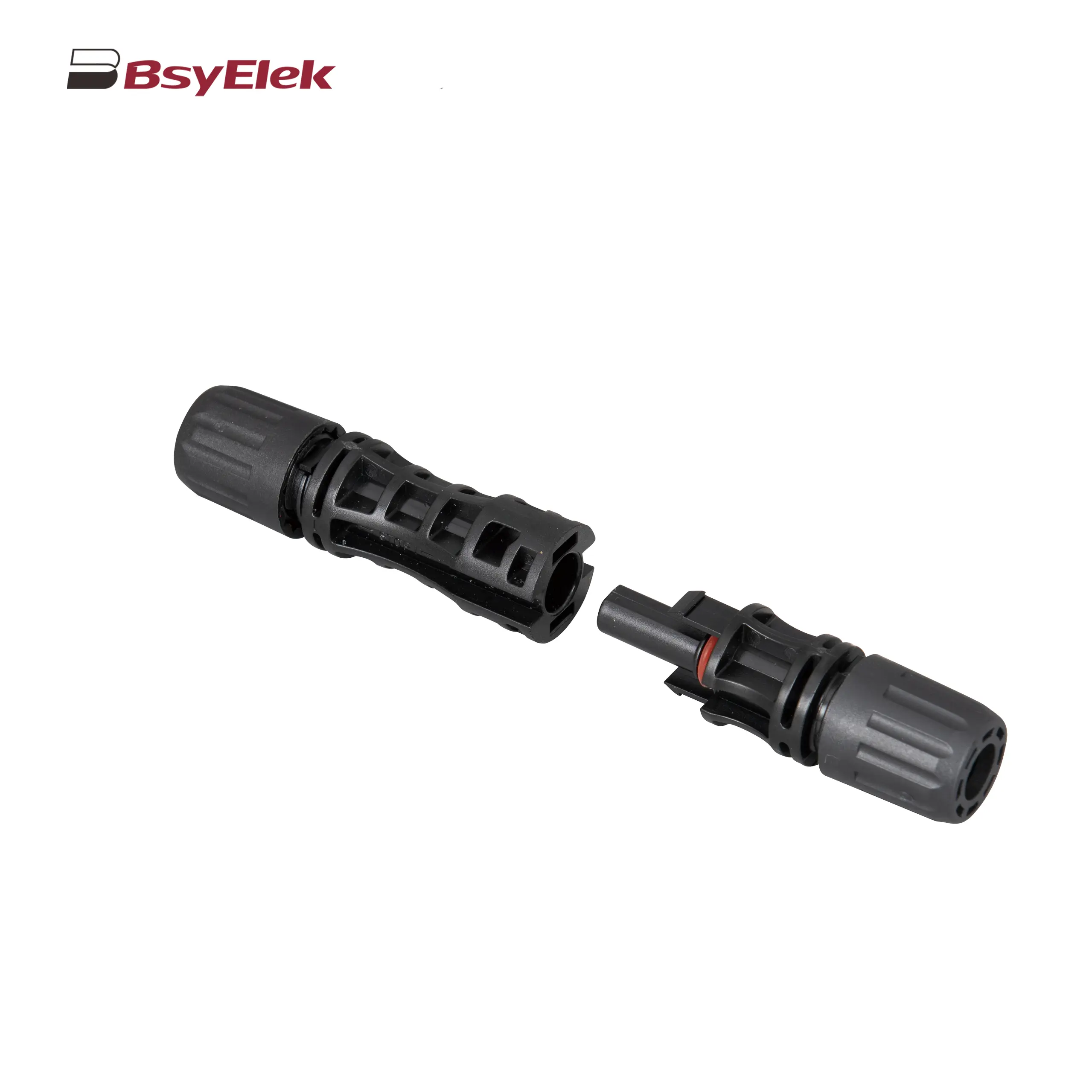 PV-BY-02 30A/50A 1500V Photovoltaic Connector
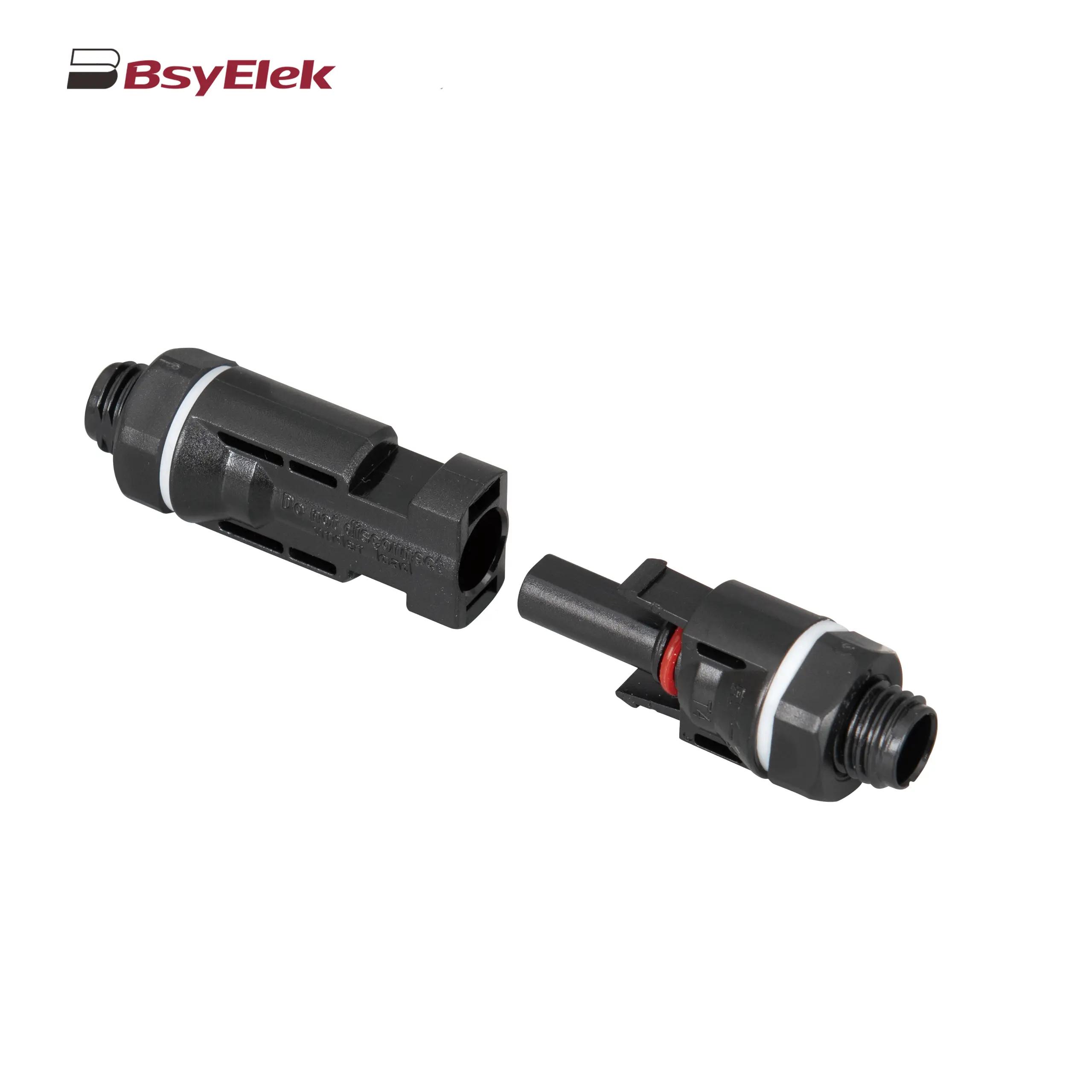 PV-BY-03 30A/50A 1000V Panel Mount Photovoltaic Connector
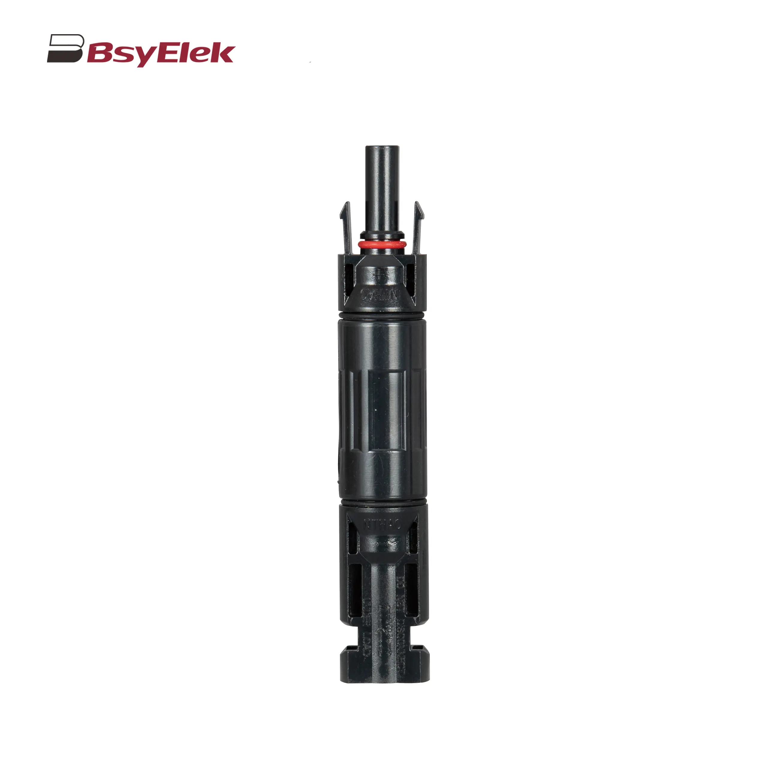 PV-BY-F01 30A 1500V Diode/Fuse Type Connector
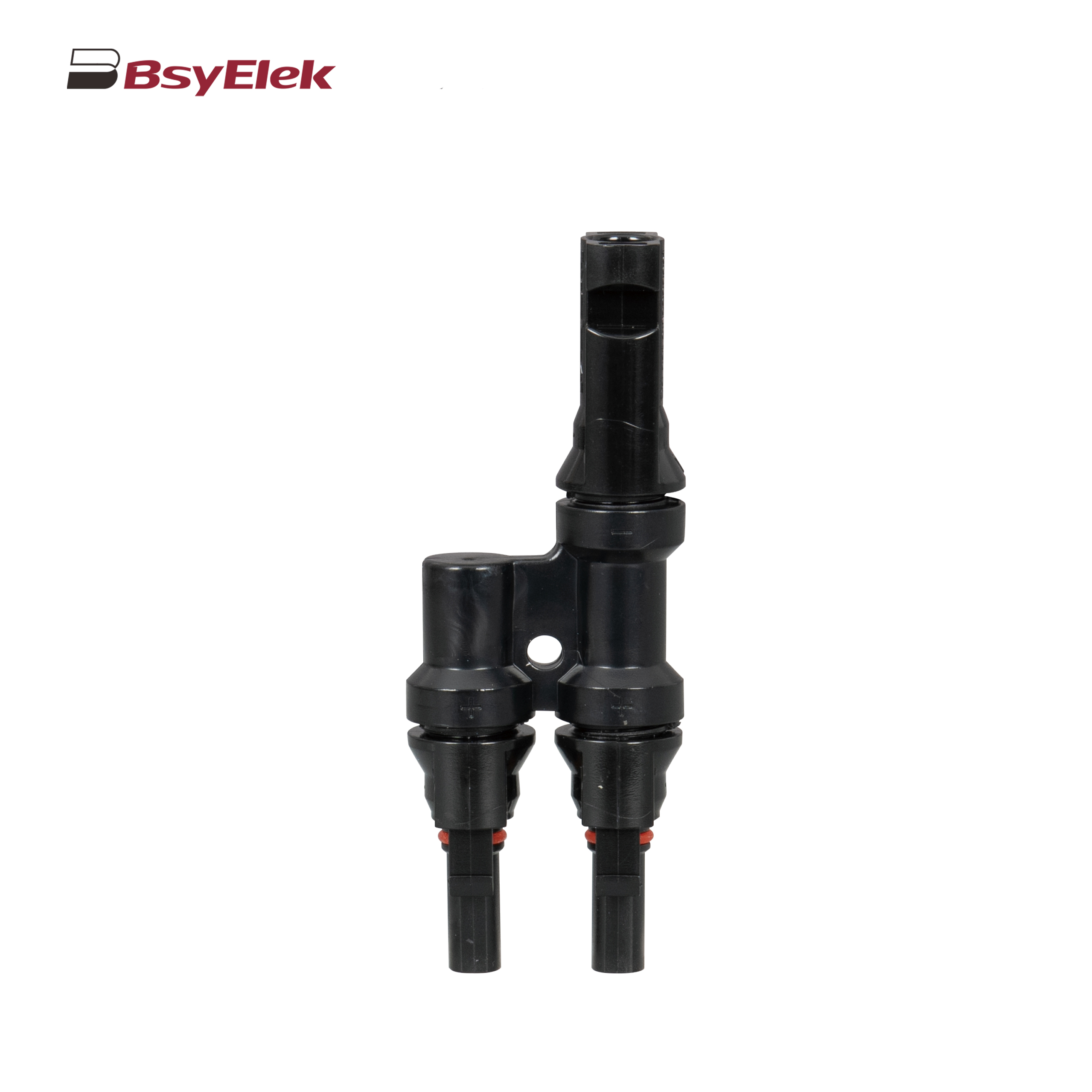 PV-BY-T 50A 1500V T Type Branch Connector
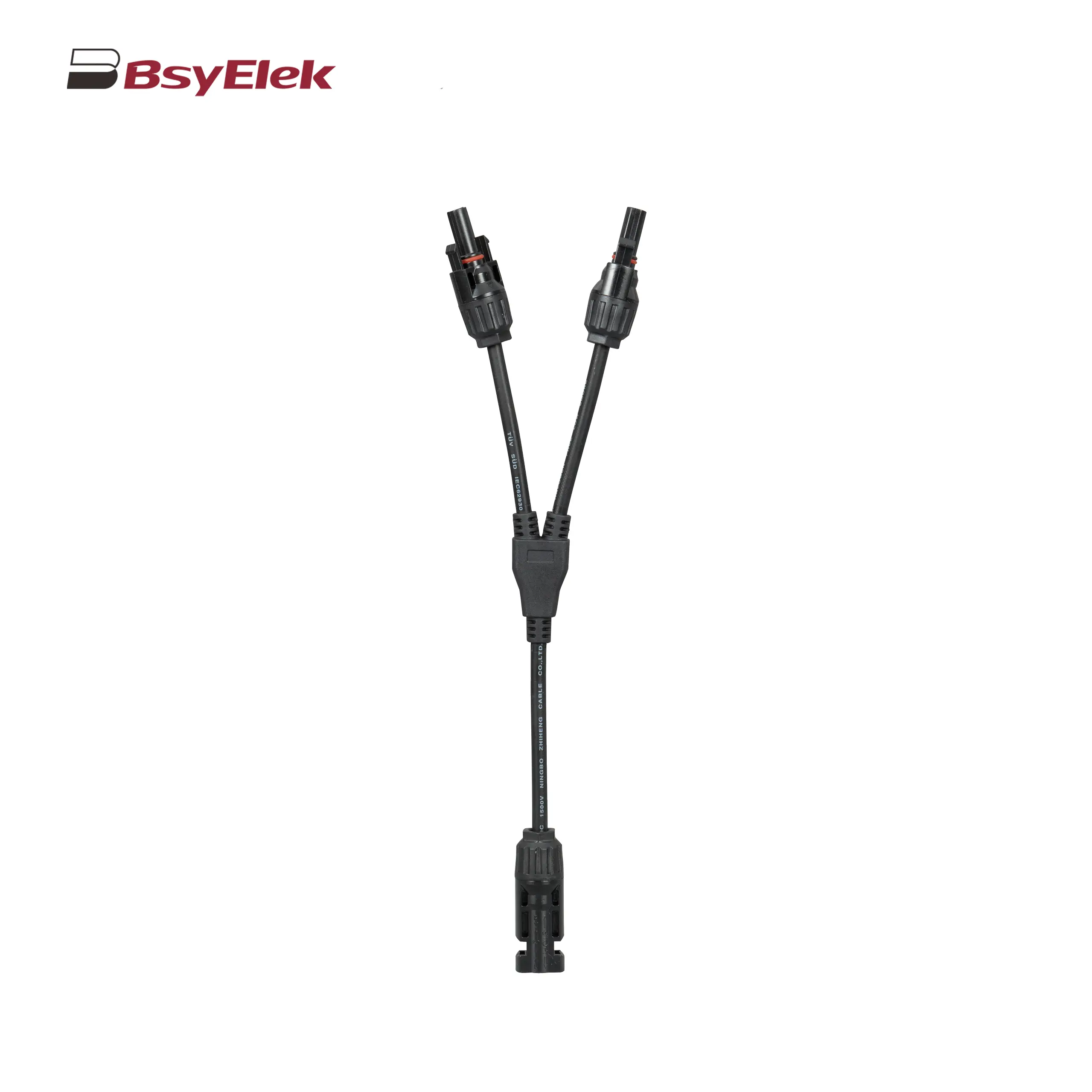 PV-BY-Y 30A 1500V Y Type Branch Connector
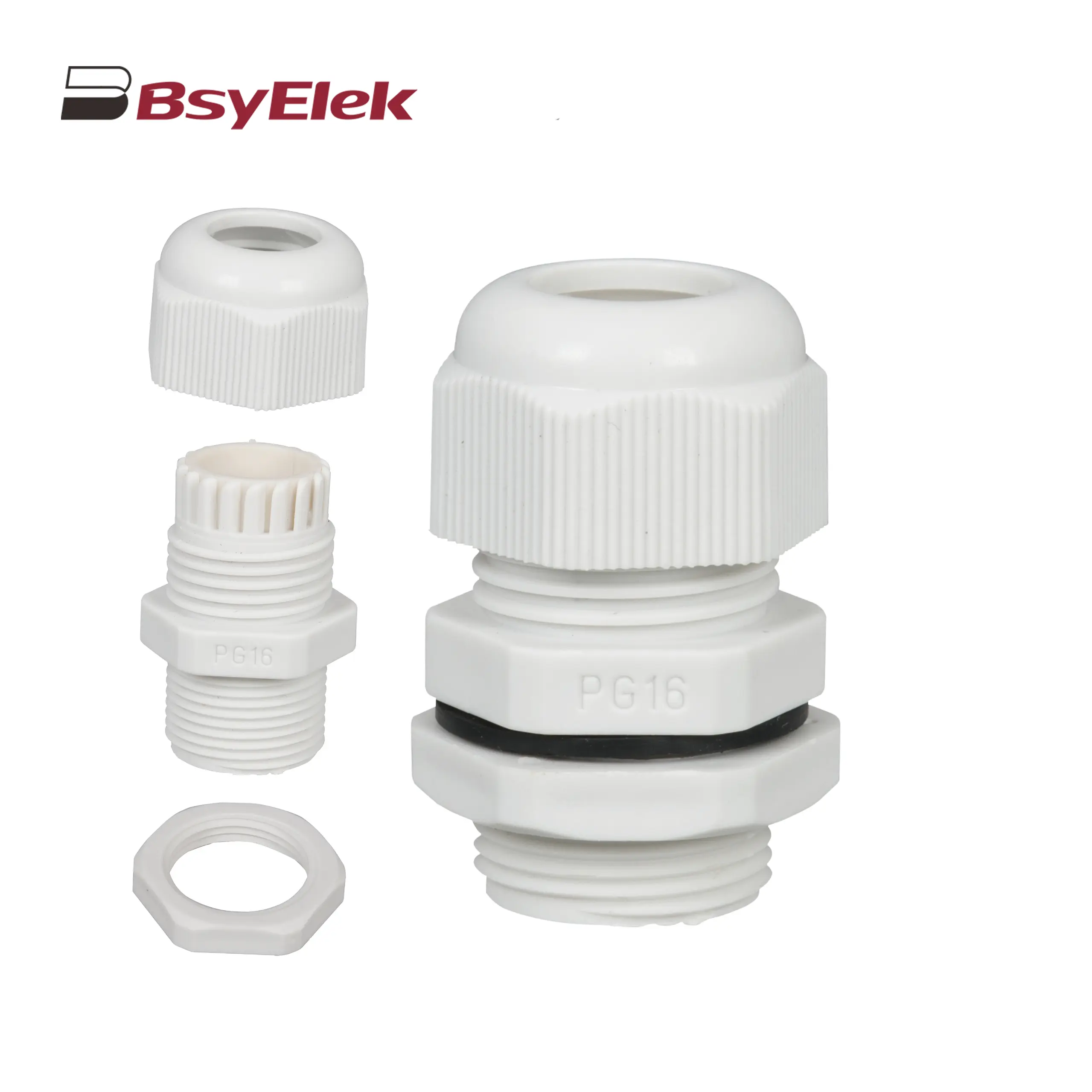 PG Waterproof Cable Gland with Washer
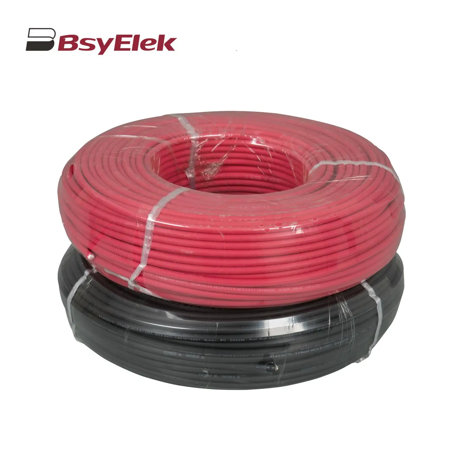 Photovoltaic Cable
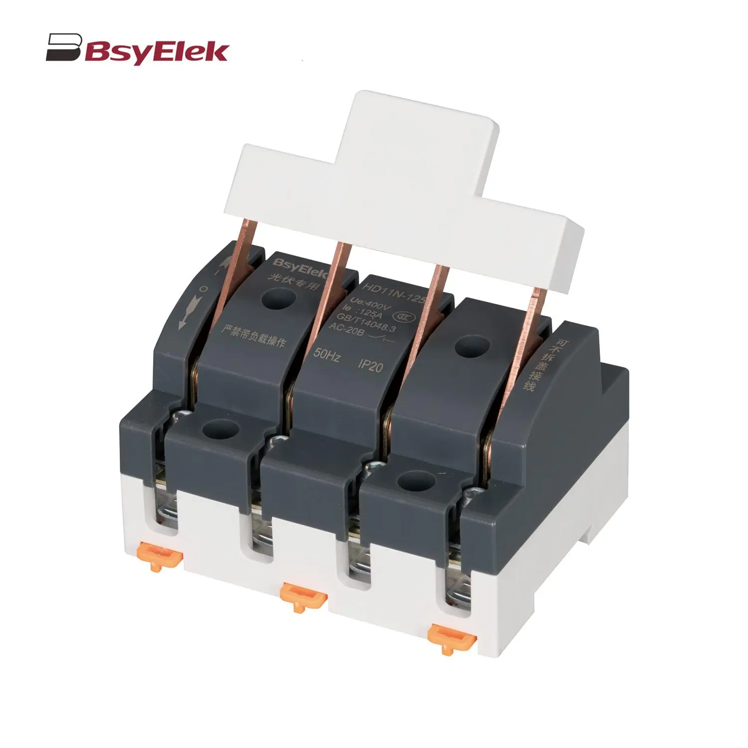 HD11N Photovoltaic Knife Switch
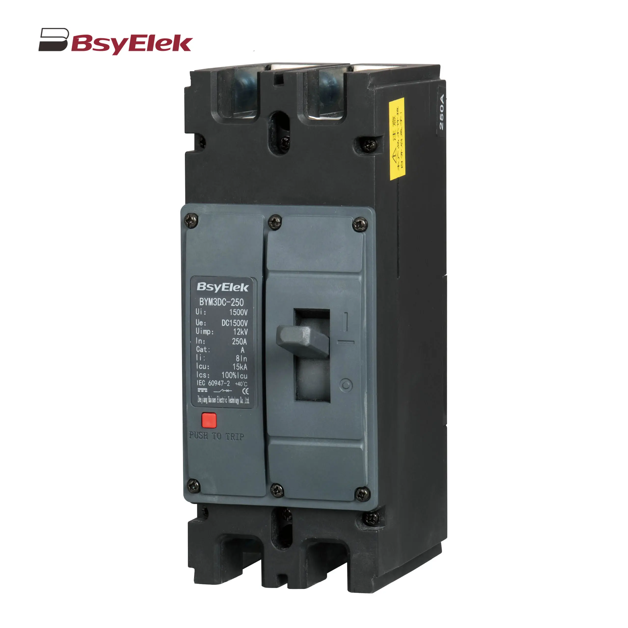 BYM3DC MCCB Photovoltaic DC Molded Case Circuit Breaker
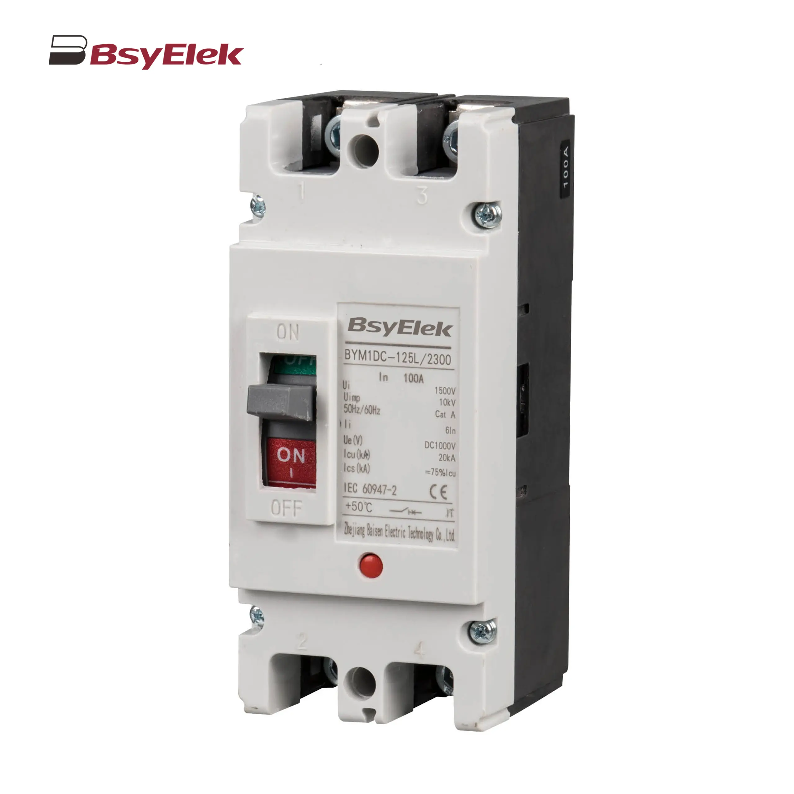 BYM1DC MCCB 1000VDC Thermal Magnetic Type DC Molded Case Circuit Breaker
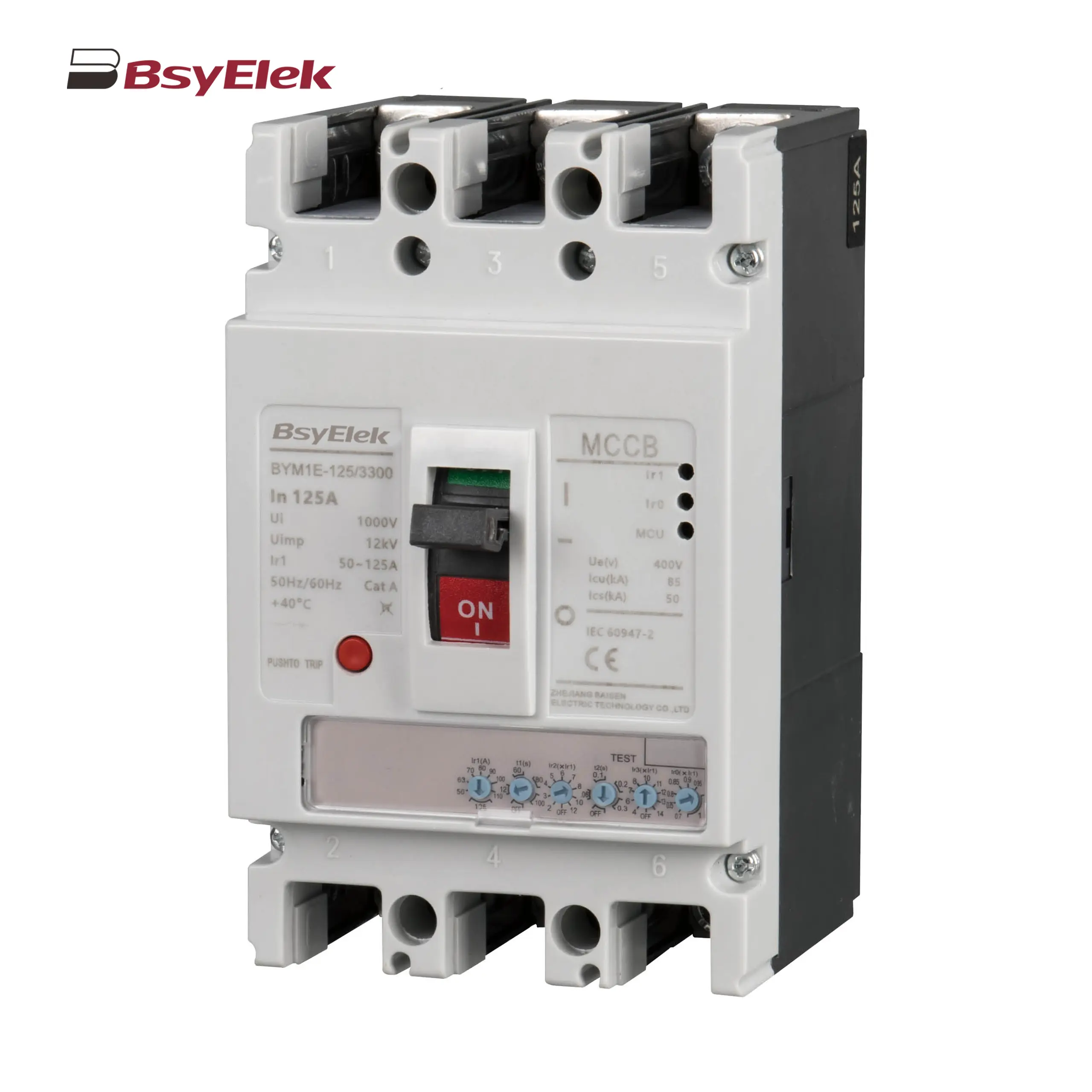 BYM1E MCCB Electronic Type Molded Case Circuit Breaker
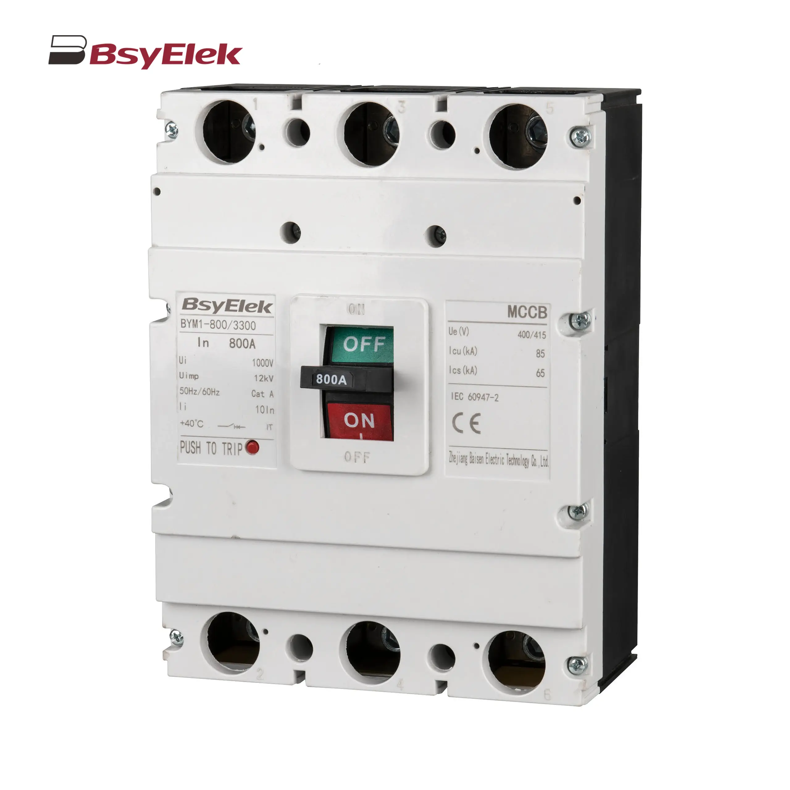 BYM1 MCCB Thermal Magnetic AC Molded Case Circuit Breaker
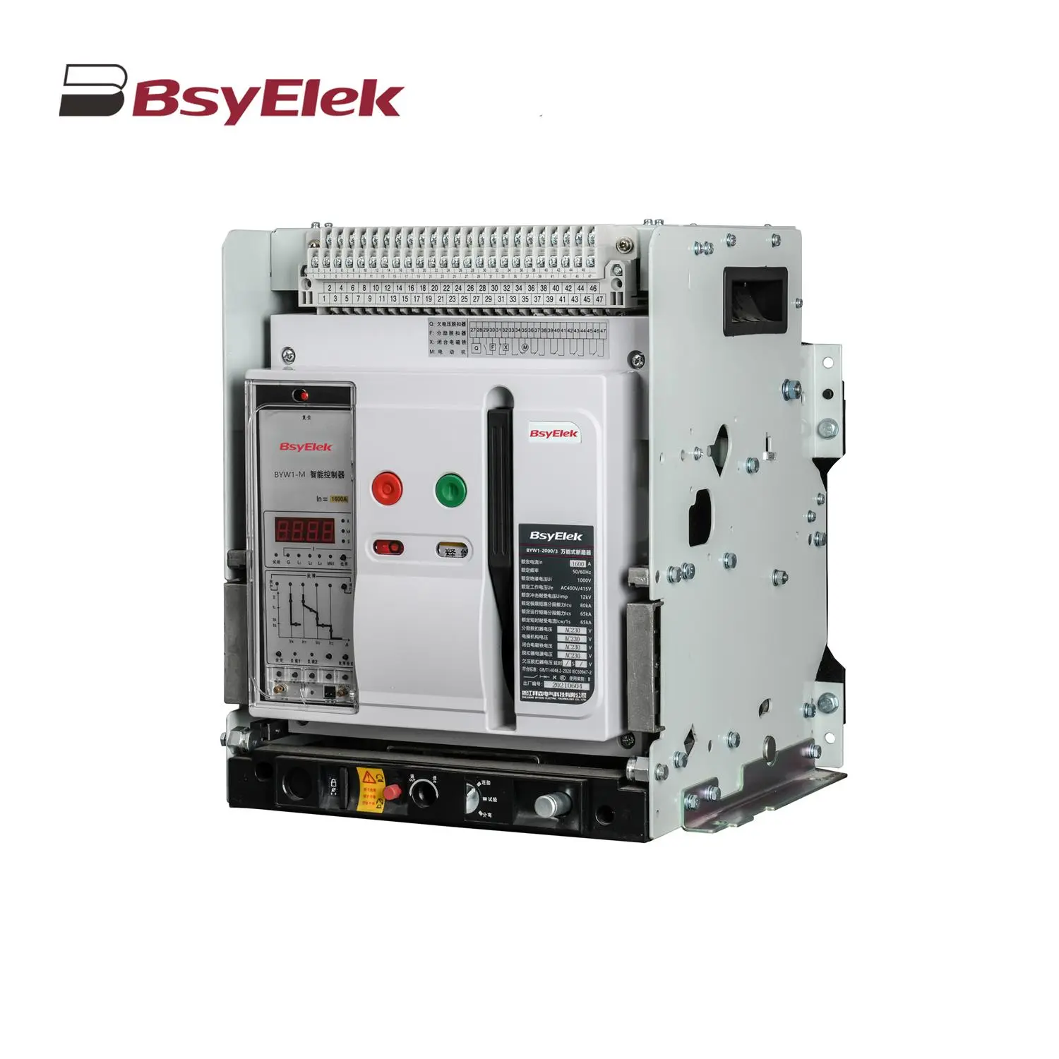 BYW1 ACB Intelligent Universal Air Circuit Breaker
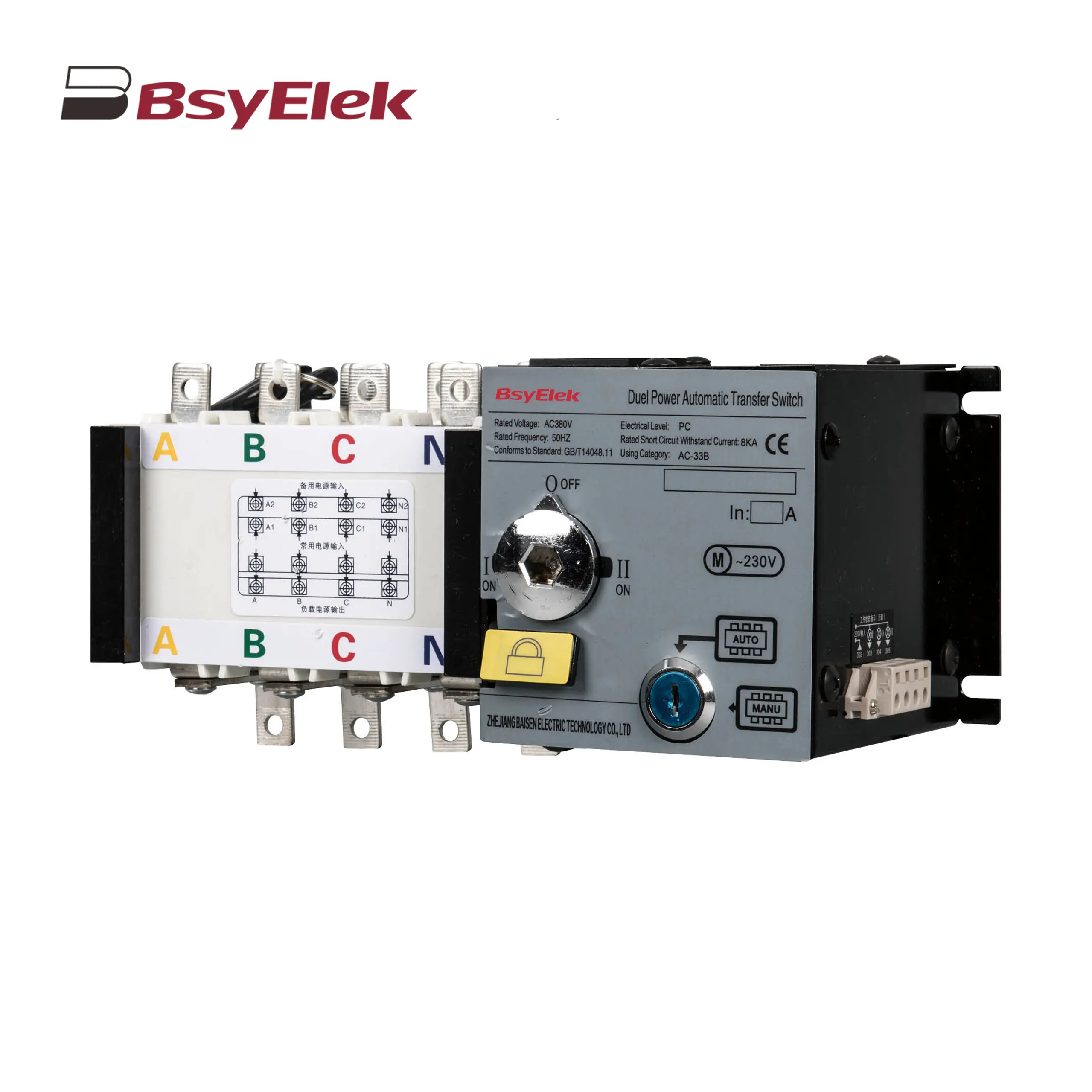 BYQ1 ATS Isolated Type PC Level Dual Power Automatic Transfer Switch
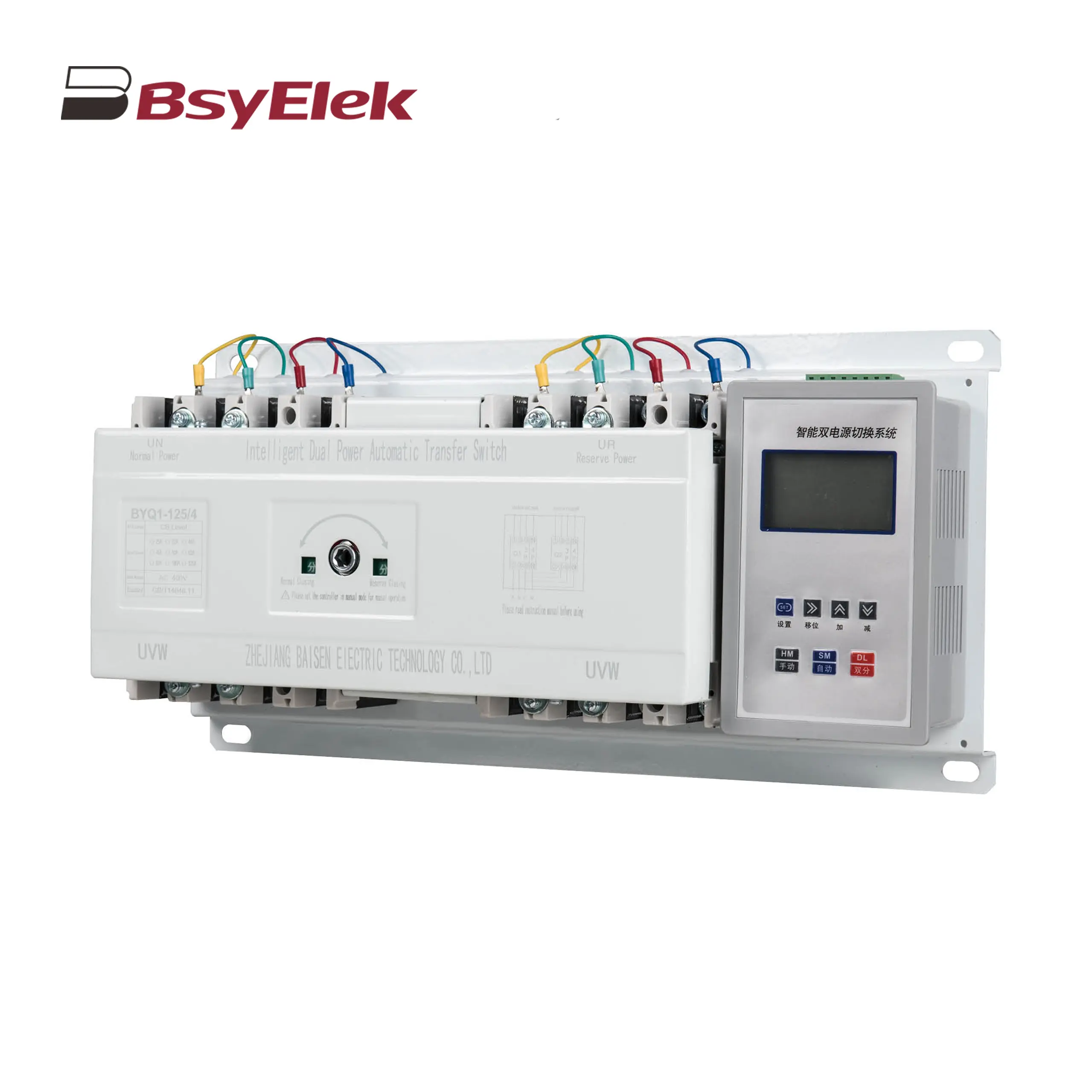 BYQ1 ATS Intelligent Type CB Level Dual Power Automatic Transfer Switch
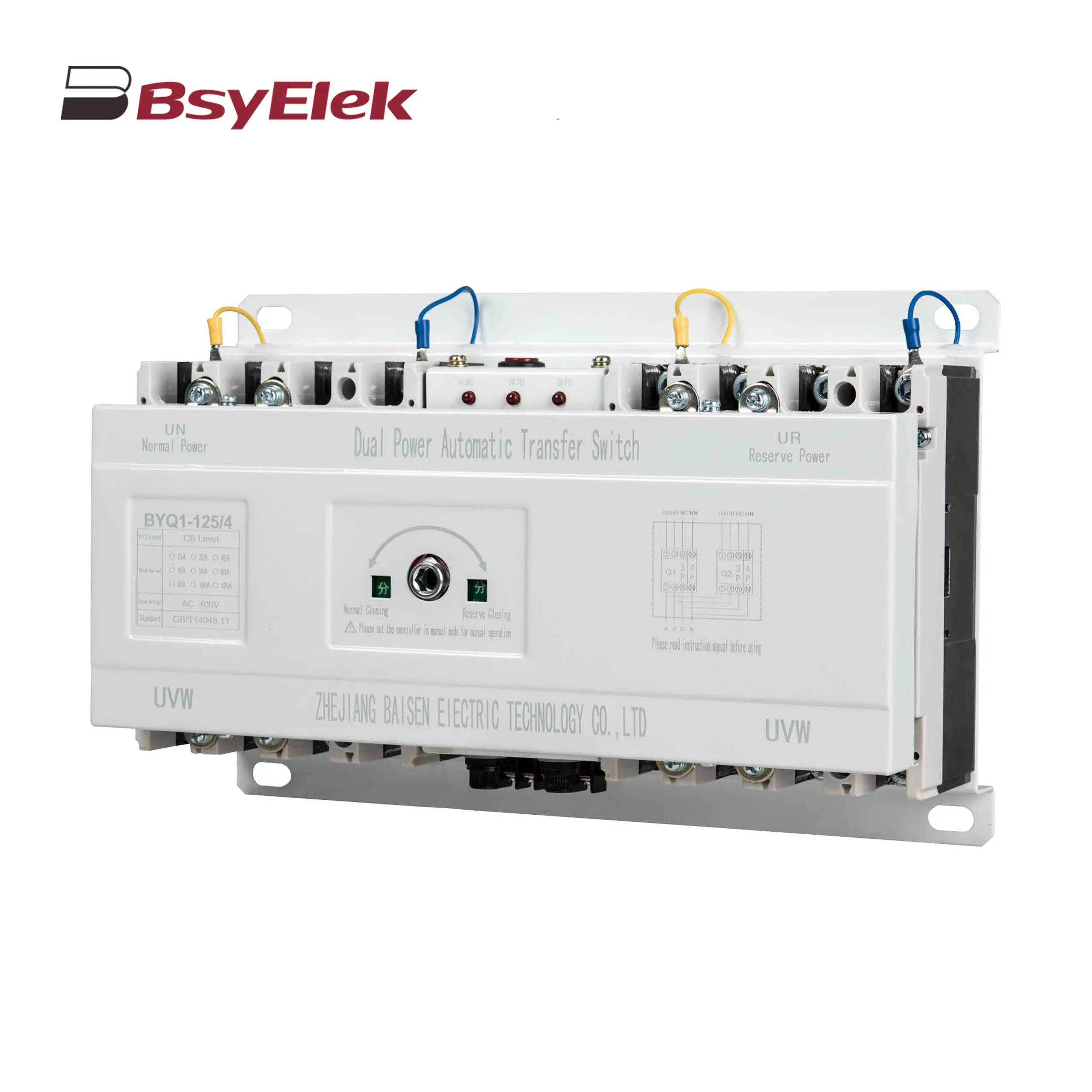 BYQ1 ATS End Type CB Level Dual Power Automatic Transfer Switch
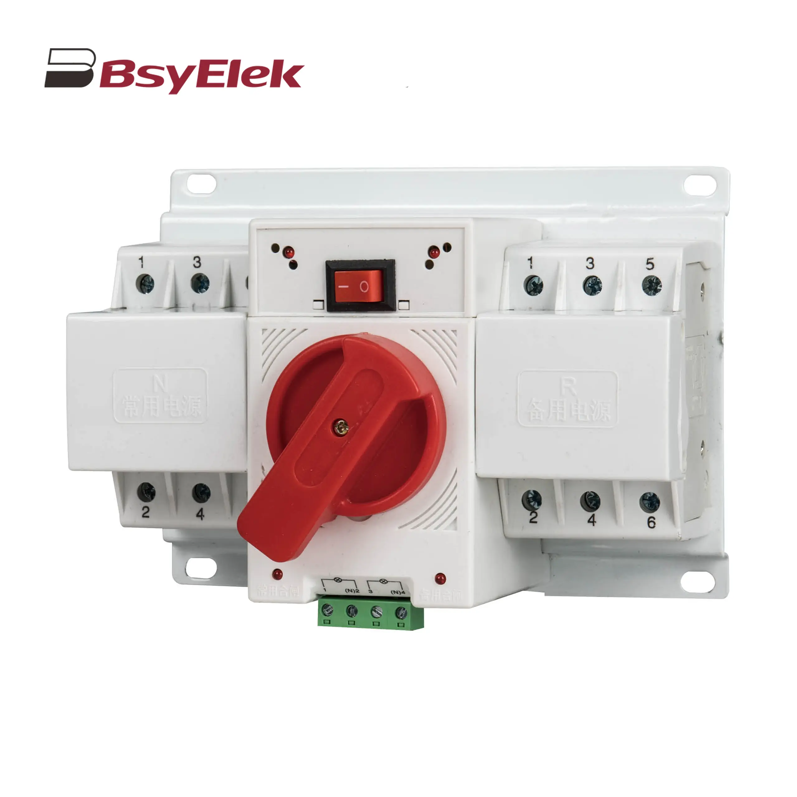 BYQ1 ATS Mini Type CB Level Dual Power Automatic Transfer Switch
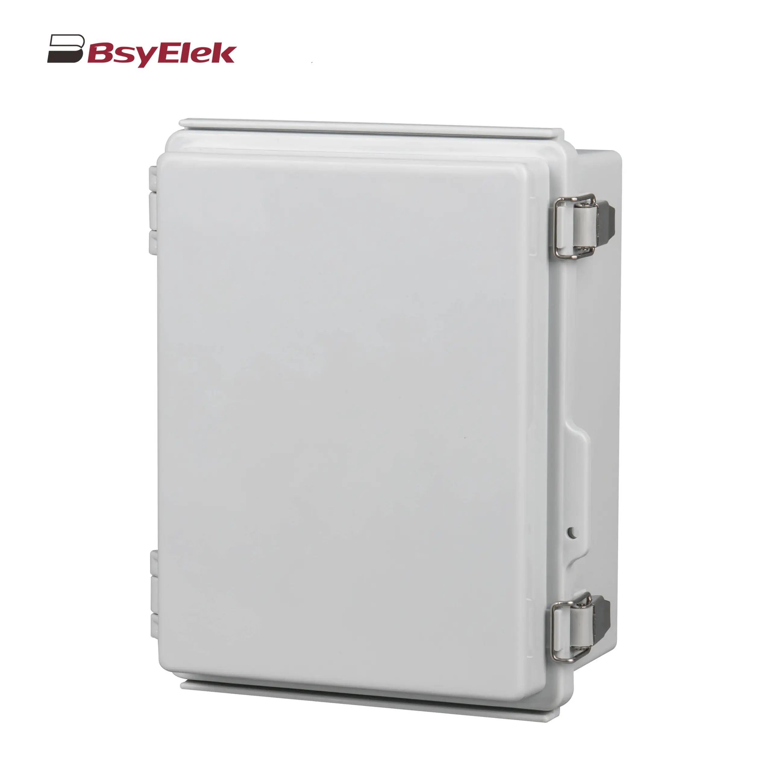 Stainless Steel Hinge Type Electrical Box
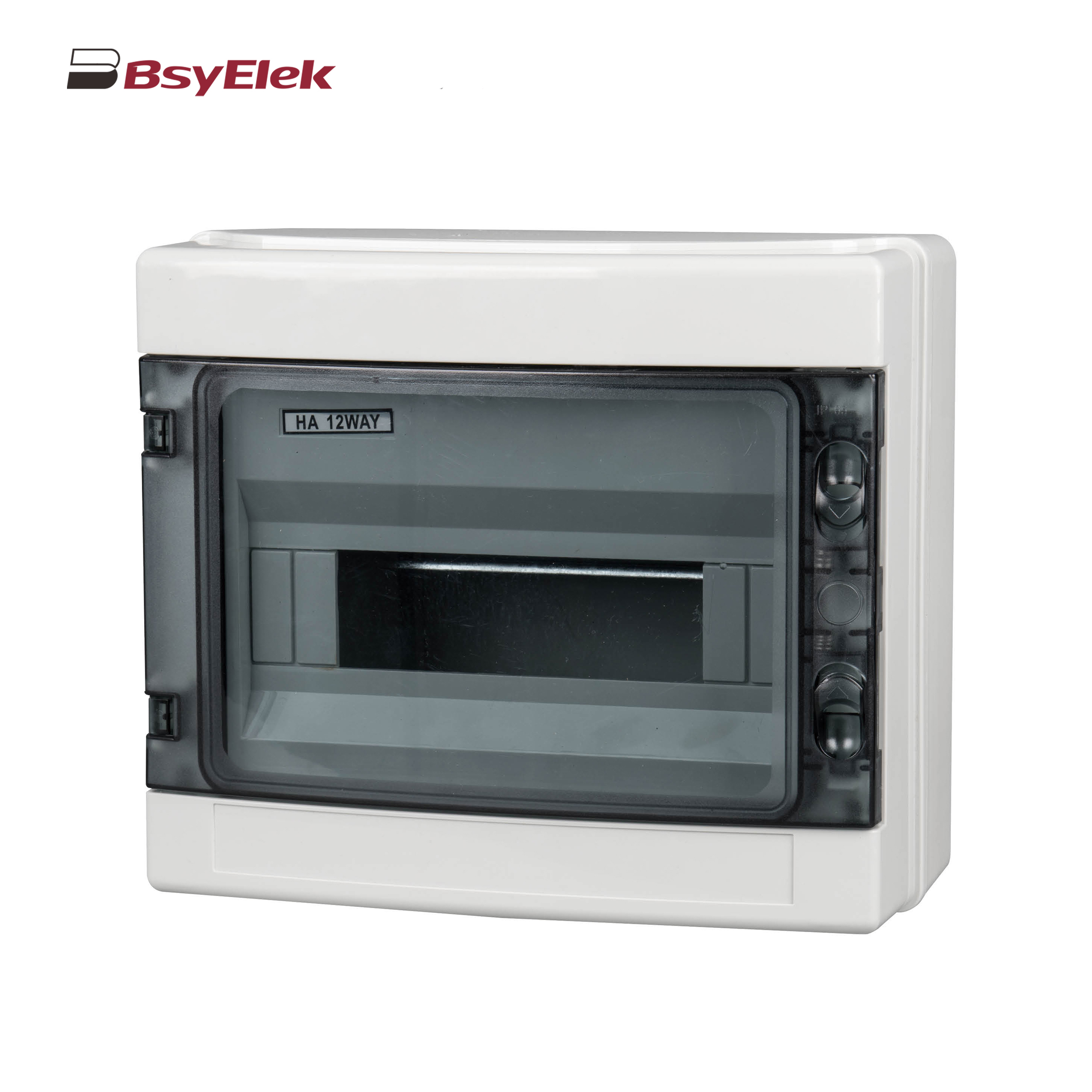 HA Waterproof Distribution Box
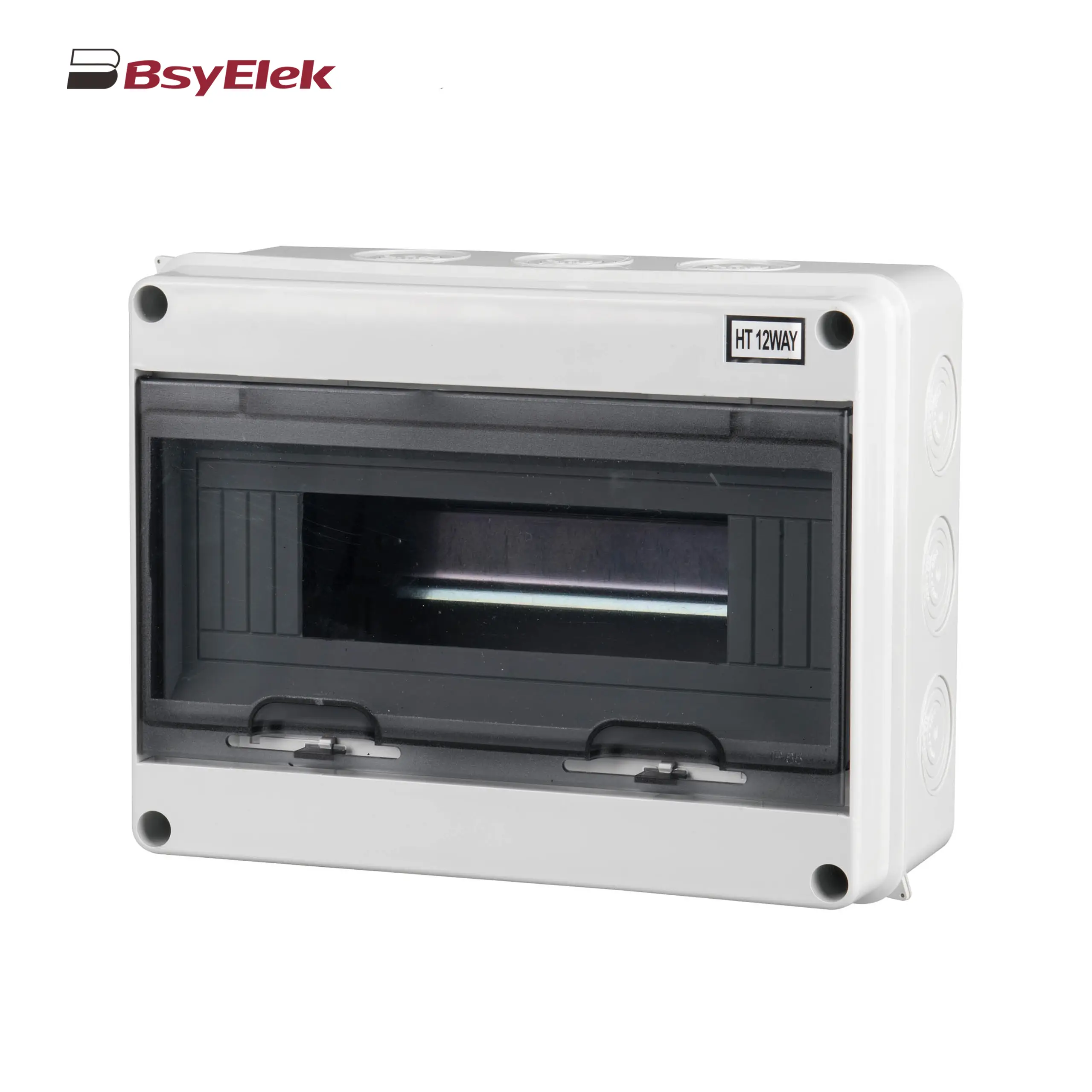 HT Waterproof Distribution Box
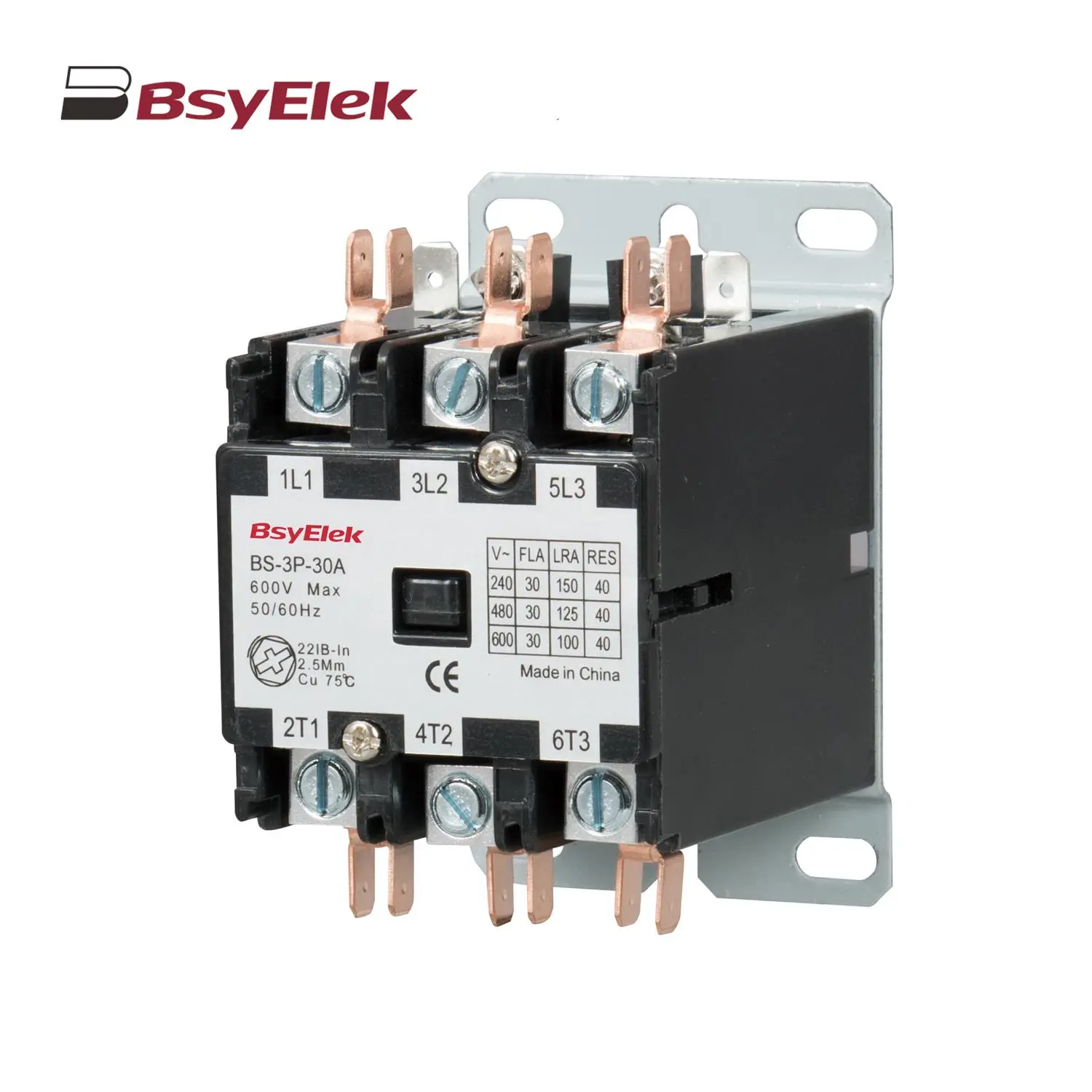 BS Definite Purpose Magnetic AC Contactor